Table of Contents
Introduction
In industrial pipeline engineering, flow control is not just about opening or closing a line—it directly affects system stability, energy efficiency, and long-term operational safety. Among the many valve types used today, the flange butterfly valve is widely adopted because it offers a practical balance between compact structure, reliable sealing, and ease of installation in medium to large diameter pipelines.
Rather than treating it as a general-purpose component, engineers increasingly evaluate flange butterfly valves based on system conditions such as pressure class, media characteristics, installation constraints, and automation requirements. This guide breaks down those considerations in a structured, field-oriented way, based on real manufacturing and application logic rather than theory alone.
Core Structure: Why the Design Still Dominates Industrial Pipelines
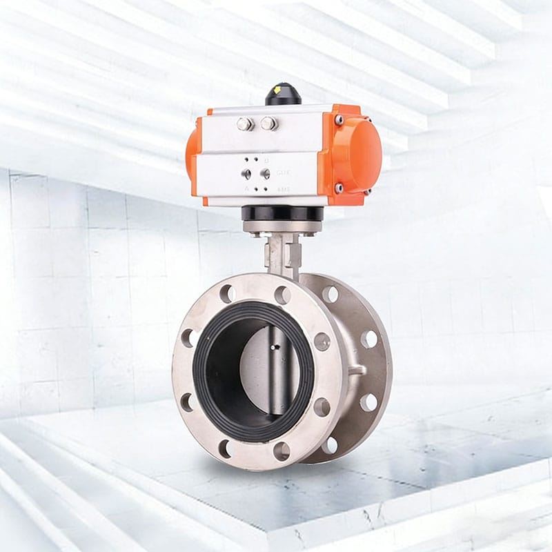
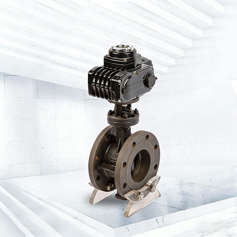
At first glance, the flange butterfly valve looks simple. A disc sits inside the pipeline and rotates to control flow. But the engineering behind this simplicity is what makes it widely applicable.
A closer look at its structure reveals four functional zones:
- Body structure: connects directly to pipeline flanges, ensuring mechanical stability
- Disc element: controls flow regulation through 90-degree rotation
- Seat system: responsible for sealing performance under pressure
- Stem and drive interface: transfers torque from actuator to disc
What makes this design effective is not just compactness, but the way it minimizes internal flow resistance when fully open. In large-scale pipeline systems, even small efficiency gains in flow behavior can translate into measurable operational improvements.
Manufacturing Perspective: Where Performance Is Actually Determined
In practice, the reliability of a flange butterfly valve is not defined at installation—it is determined long before that, during production.
A typical industrial manufacturing process includes several tightly controlled stages:
Material selection is the first critical step. Different operating environments demand different material behaviors. Ductile iron is often selected for general water systems, while stainless steel becomes necessary in corrosive or chemically aggressive environments.
Casting quality follows closely behind. Internal porosity, wall thickness uniformity, and structural density all influence pressure resistance. Poor casting control often leads to long-term sealing instability rather than immediate failure.
Machining and finishing define how well sealing surfaces interact. Even minor deviations in disc edge geometry can affect torque behavior and seat wear over time.
Before shipment, valves undergo a series of functional validations, including:
- shell pressure verification
- seat sealing evaluation
- repeated actuation cycles under load conditions
From a manufacturing standpoint, consistency matters more than individual performance. Industrial buyers usually experience issues not from isolated defects, but from batch-level variation.
Flange Connection Advantage: Stability in Real Pipeline Conditions
Compared with other installation types, the flange connection structure offers a clear mechanical advantage in systems exposed to vibration, pressure fluctuation, or long pipeline spans.
The bolted flange interface helps distribute stress evenly across the connection point. This reduces localized deformation that can affect sealing integrity over time.
In field installations, flange-connected butterfly valves are often preferred in:
- large-diameter water transmission pipelines
- pump station outlet systems
- industrial circulation loops
- long-distance fluid transport lines
The key advantage is not just strength, but predictability. Once installed correctly, the system maintains alignment stability over long operational cycles.
Wafer vs Flange Design: A Practical Engineering Comparison
Although both designs serve similar functions, they behave differently once integrated into a system.
The wafer type relies on being sandwiched between two pipeline flanges. This reduces installation space but increases dependency on external alignment accuracy.
The flange type, on the other hand, integrates bolting directly into its structure. This provides better rigidity and makes it more suitable for systems where pipeline stress cannot be fully controlled.
In practical engineering terms:
- wafer design fits compact or auxiliary systems
- flange design fits primary or high-stability pipeline networks
This distinction is often overlooked during procurement but becomes significant during long-term operation.
Pressure Ratings: Why PN Classification Matters More Than Expected
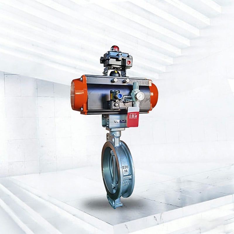
Pressure classification is not just a specification detail—it defines how the valve behaves under real operating stress.
Common industrial categories include PN10, PN16, and PN25, each representing different structural reinforcement levels.
However, the more important consideration is not the number itself, but how pressure interacts with temperature, flow velocity, and media type.
For example:
- clean water systems operate with stable pressure distribution
- slurry or particulate media introduces dynamic pressure fluctuation
- chemical systems may experience thermal expansion effects
These factors influence seat compression, disc stability, and stem torque behavior. Selecting a pressure class without considering system dynamics often leads to premature wear or inconsistent sealing.
Application Mapping: Where Flange Butterfly Valves Actually Perform Best
Instead of listing industries in isolation, it is more useful to understand how operating conditions define suitability.
In water treatment systems, the valve is typically used for isolation and flow balancing. Stability and low maintenance requirements are more important than extreme pressure resistance.
In HVAC systems, the focus shifts toward responsive flow control and energy efficiency across circulation loops.
In oil and gas or chemical environments, material compatibility becomes the deciding factor, especially under corrosive or high-temperature conditions.
Across all applications, one consistent requirement remains: predictable performance over repeated cycles.
Installation Reality: What Engineers Focus on in the Field
Installation is often underestimated in documentation but is critical in practice.
Most operational issues do not originate from valve design, but from installation inconsistencies such as misalignment, uneven bolt tightening, or gasket displacement.
Field experience highlights several practical points:
- flange faces must remain parallel during tightening
- torque should be applied gradually in cross sequence
- disc movement should be checked before full system pressurization
- pipeline stress should not be transferred to the valve body
Even a well-manufactured valve can underperform if installation conditions are not properly controlled.
Maintenance Logic: Extending Operational Stability
Maintenance is not only about fixing issues but about preventing performance drift over time.
In real operating environments, most valves degrade gradually rather than failing suddenly. This is usually reflected in increased operating torque, slight leakage, or slower response during actuation.
Common preventive practices include:
- periodic sealing surface inspection
- stem lubrication under operating cycles
- removal of sediment accumulation in disc area
- verification of actuator responsiveness
The goal is not replacement, but maintaining consistent operational behavior across long service periods.
Manufacturer Role: Why Source Consistency Matters in Industrial Projects
In industrial procurement, the difference between suppliers often appears only after long-term use.
A direct manufacturing source typically provides:
- consistent material traceability across batches
- controlled machining tolerances
- application-based customization options
- standardized testing procedures
- technical support aligned with engineering requirements
This becomes particularly important in large pipeline projects where multiple valve units must behave uniformly under identical conditions.
Selection Perspective: A Practical Engineering Checklist
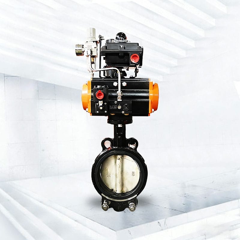
Instead of treating selection as a catalog decision, engineers usually evaluate valves through system behavior:
- What type of media is flowing through the pipeline?
- Is the system stable or subject to fluctuation?
- How frequently will the valve operate?
- Is automation required in control logic?
- What level of maintenance access is available?
These questions often determine performance outcomes more accurately than specification sheets alone.
Conclusion
The flange butterfly valve continues to be a foundational component in industrial pipeline systems because it adapts well to varied operating environments while maintaining mechanical simplicity. Its performance is not defined by structure alone, but by how well it matches system conditions such as pressure behavior, media characteristics, and installation quality.
For engineering teams and industrial buyers, the key is not simply selecting a valve type, but ensuring that design, manufacturing consistency, and application requirements are aligned. When these elements are properly matched, the valve becomes a stable and predictable part of the system rather than a maintenance concern.
FAQ
Q1: What is a flange butterfly valve used for?
A flange butterfly valve is used to control or isolate fluid flow in pipeline systems, commonly in water treatment, HVAC, and industrial processing lines.
Q2: What is the difference between flange and wafer butterfly valves?
Flange butterfly valves connect directly to pipeline flanges for higher stability, while wafer types are clamped between flanges and require less installation space.
Q3: How does a flange butterfly valve work?
It uses a rotating disc connected to a stem. A 90-degree turn changes the valve from fully open to fully closed, regulating flow inside the pipeline.
Q4: What pressure ratings are common for flange butterfly valves?
Common pressure classes include PN10, PN16, and PN25, depending on system requirements such as pressure level, media type, and operating conditions.
Q5: What are the key factors when selecting a flange butterfly valve?
Important factors include pipeline size (DN), pressure rating, sealing material, actuator type, and the specific application environment.