A three-way valve quotation can look complete while leaving one crucial question unanswered: which ports are connected at each position? Discovering that mismatch during commissioning is an expensive way to finish the specification.
Choose a pneumatic three-way ball valve by defining the required flow paths first, then checking transition behavior, pressure conditions, materials, actuator failure position and control feedback. Size and connection details matter, but they cannot tell the supplier how your process must switch.
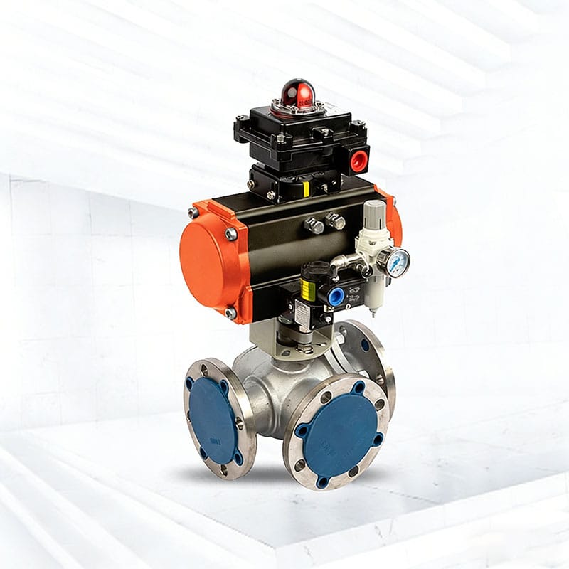
This guide focuses on preparing a workable purchase specification for the Phileda pneumatic three-way ball valve. The product is offered for automated flow switching; the exact port arrangement and operating limits need confirmation in the proposal.
Draw the connections for every operating position
For example, a cooling-water header may need to supply either a duty heat exchanger or a standby heat exchanger. On the inquiry drawing, label the cooling-water inlet A, the duty heat exchanger connection B and the standby heat exchanger connection C. Specify the required routing as follows.
| Cooling-water operating condition | Required flow path | Requirement to confirm with the supplier |
|---|---|---|
| Duty heat exchanger in service | Cooling-water header inlet → duty heat exchanger inlet (A to B) | The standby heat exchanger connection must remain isolated. |
| Standby heat exchanger in service | Cooling-water header inlet → standby heat exchanger inlet (A to C) | The duty heat exchanger connection must remain isolated. |
| Changeover between heat exchangers | Cooling-water supply transfers from the duty unit to the standby unit. | Confirm whether flow interruption or temporary supply to both units is acceptable, and verify the offered valve’s behavior during travel. |
| Loss of instrument air or solenoid power | The required cooling-water route must be defined by the process safety review. | State which exchanger must remain supplied and which connection must be isolated; have the complete assembly’s response confirmed. |
This is an illustrative switching requirement, not a port diagram for every Phileda valve. Have the supplier return the actual flow diagram with port labels, rotation direction and actuator positions. For the basic bore arrangements, see our L-port vs T-port comparison.
Check what happens between the end positions
Two correct end positions do not establish a suitable changeover. Ask whether any ports communicate during travel and whether the flow is temporarily interrupted. These details can matter when switching between tanks, pumps or different fluids.
Describe any restriction on cross-connection, backflow or interruption. If the duty requires positive segregation, have the piping and isolation arrangement reviewed rather than relying on the words “three-way valve.” A switching valve’s normal operating function does not by itself establish a maintenance isolation boundary.
Provide pressures at all three connections
A single line-pressure figure can hide the demanding operating case. State the pressure at A, B and C for each operating mode, including startup and shutdown. Identify the maximum differential pressure against which the valve must move or seal.
Include any possibility of reverse pressure from a branch. Ask the supplier to confirm the approved pressure directions, shutoff conditions and leakage acceptance criteria. The pressure boundary rating and the seat’s allowable differential pressure answer different questions.
For flow capacity, provide the required flow through each route, the fluid properties and the allowable pressure loss. Matching the existing pipe size alone is not a capacity check.
Check materials against every fluid
A valve that alternates between process fluid and cleaning solution must suit both. Supply composition, concentration, normal temperature and cleaning conditions. Include particles, viscosity and deposits that could affect the ball or seats.
Request the wetted-parts list, including ball, seats, stem and seals. Phileda lists soft- and metal-seated configurations for this product family; ask which is proposed and why it suits the stated conditions. Do not infer a temperature limit or chemical compatibility from the family name.
Define failure position and air supply together
Write down the required flow path after loss of instrument air, power to the solenoid and the control signal. Avoid specifying only “fail-open”: on a three-way valve, that leaves the destination unclear.
Instead, describe the required connection—for example, A connected to B with C isolated—then have the supplier confirm whether the offered assembly achieves it. Give the minimum available air pressure at the actuator, operating frequency and required switching time.
Confirm the actuator travel and controls for every required position. A standard two-position package should not be assumed to provide an additional controlled position. Spring-return and double-acting arrangements also require different failure-response reviews.
Ask for feedback that identifies the flow path
Operator displays should make the valve’s function understandable. A generic “open” indication can be ambiguous when either of two branches may be connected. Define the required local and remote position indications alongside the port diagram.
List solenoid voltage, control signal, feedback contacts, enclosure requirements and any project-specific approvals. Request the wiring or pneumatic schematic and assembly drawing before purchase approval. Check that the actuator and accessories have enough maintenance clearance in the installed orientation.
A useful three-way valve inquiry
Send the following information with your request for quotation:
- Quantity, nominal size, connection standard and installation dimensions.
- A labeled port sketch and required connections at each position.
- Restrictions on communication or interruption during travel.
- Fluid composition and operating and cleaning temperatures.
- Pressures at every port, maximum differential pressure and flow per route.
- Minimum air supply, switching time, frequency and required failure path.
- Solenoid, feedback, documentation and test requirements.
For a replacement, attach the old valve nameplate and flow diagram. A photograph of the outside is useful for layout, but it cannot establish the internal flow path.
Need an assembly matched to your switching duty? Send Phileda your port diagram and request a pneumatic three-way ball valve quotation. Ask for the proposed flow diagram, materials, actuator configuration and test scope with the offer so the alternatives can be compared on the same basis.
FAQ
What is a pneumatic three-way ball valve used for?
It switches or routes flow among three connections using a pneumatic actuator. The permitted connections depend on the internal port arrangement and actuator positions supplied.
Can every three-way ball valve mix two streams?
No. Confirm that the port arrangement permits the required simultaneous connections and that the valve is suitable for the pressure and control duty. Routing capability alone does not establish controlled mixing performance.
How should I specify the failure position?
Identify the ports that must communicate and those that must be isolated after each utility failure. Have the supplier confirm that response for the complete actuator and control package.
What is the most important drawing to request?
Request a flow-path diagram showing the labeled ports at each operating position and the connections during travel, together with the assembly dimensions and control schematic.