Control valve sizing is one of the most important steps in designing a reliable industrial process control system. A correctly sized valve helps maintain stable flow, pressure, temperature, and liquid level while reducing unnecessary wear and control problems.
However, selecting a control valve based only on pipe diameter or maximum flow can lead to poor regulation, excessive noise, cavitation, and premature component failure.
For engineers and industrial buyers, proper control valve sizing requires an understanding of flow coefficient (Cv or Kv), operating pressure differential, fluid properties, valve characteristics, and actuator requirements.
This guide explains how to size a control valve, calculate Cv for liquid applications, evaluate pressure drop, and prepare the technical information needed before requesting a quotation.
Table of Contents
What Is Control Valve Sizing?
Control valve sizing is the process of determining the flow capacity required for a valve to regulate a process under specified operating conditions.
The objective is not simply to find a valve large enough to pass the maximum flow. A properly sized control valve must also provide stable regulation during minimum and normal operating conditions.
For example, a valve that handles maximum flow but operates almost fully closed during normal production may provide poor control performance.
Similarly, an undersized valve may be unable to deliver the required flow when production demand increases.
The correct control valve size is determined by process flow requirements and available pressure differential, not by pipe diameter alone.
A complete sizing assessment should consider:
- Minimum, normal, and maximum flow rates
- Upstream and downstream operating pressures
- Fluid temperature and physical properties
- Required flow coefficient
- Valve flow characteristics
- Cavitation, flashing, and choked-flow risks
- Actuator force or torque requirements
- Required shutoff performance
These factors determine whether a proposed valve can provide reliable regulation throughout its expected operating range.
What Is Cv in Control Valve Sizing?
Cv is a flow coefficient used to express the capacity of a control valve.
In US customary units, Cv represents the flow rate of water, in US gallons per minute, passing through a valve at a pressure drop of 1 psi under the standard reference conditions.
A higher Cv generally indicates a greater flow capacity.
However, Cv does not directly indicate valve quality, control accuracy, or suitability for a particular industrial application.
Two valves with similar rated Cv values may have different flow characteristics, pressure recovery behavior, noise performance, and leakage classifications.
What Is the Difference Between Cv and Kv?
Cv and Kv describe valve flow capacity using different reference units.
| Parameter | Cv | Kv |
|---|---|---|
| Common usage | US customary units | Metric units |
| Reference flow | US gallons per minute | Cubic meters per hour |
| Reference pressure drop | 1 psi | 1 bar |
| Reference medium | Water under standard reference conditions | Water under standard reference conditions |
| Conversion | Cv ≈ 1.156 × Kv | Kv ≈ 0.865 × Cv |
The conversion is useful when comparing control valves from manufacturers using different measurement systems.
For international procurement projects, buyers should confirm whether the valve data sheet provides Cv, Kv, or both.
Why Does Cv Matter?
Cv is one of the primary inputs used to determine whether a valve can deliver the required flow.
If the selected Cv is too low, the valve may restrict the process at maximum demand.
If the selected Cv is unnecessarily high, the valve may operate within a narrow portion of its travel, reducing useful control resolution.
A suitable Cv must therefore be evaluated together with the valve’s installed flow characteristic and operating conditions.
How to Calculate Control Valve Cv for Liquids
For a simplified liquid application involving non-viscous, incompressible flow without cavitation, flashing, or choking, the required Cv can be estimated using:
Cv = Q × √(SG / ΔP)
Where:
- Cv = required valve flow coefficient
- Q = liquid flow rate in US gallons per minute (GPM)
- SG = liquid specific gravity relative to water
- ΔP = pressure drop across the valve in psi
This simplified equation is useful for preliminary calculations.
It should not replace a complete sizing assessment when the application involves high pressure drop, viscous fluids, two-phase flow, cavitation, or other demanding conditions.
Example: Control Valve Cv Calculation
Consider a water system with the following hypothetical operating conditions:
| Parameter | Value |
|---|---|
| Fluid | Water |
| Flow rate | 100 GPM |
| Specific gravity | 1.0 |
| Valve inlet pressure | 60 psig |
| Valve outlet pressure | 50 psig |
| Pressure drop | 10 psi |
The calculation is:
Cv = 100 × √(1.0 / 10)
Cv ≈ 31.6
The required operating Cv is approximately 31.6 under these assumed conditions.
This does not mean that the buyer should automatically select a valve with a rated Cv of exactly 31.6.
The next step is to evaluate the manufacturer’s available valve sizes, rated Cv values, flow characteristics, and expected operating travel.
A valve with a higher rated Cv may be appropriate if it provides suitable control at minimum, normal, and maximum operating flow.
Important: This example is an illustrative calculation, not a published performance specification for a Phileda control valve.
How to Calculate Control Valve Kv Using Metric Units
For a simplified liquid application, Kv can be estimated using:
Kv = Q × √(SG / ΔP)
Where:
- Kv = required flow coefficient in metric units
- Q = liquid flow rate in m³/h
- SG = liquid specific gravity
- ΔP = pressure drop in bar
For example, consider a water system with a flow rate of 20 m³/h and a valve pressure drop of 2 bar.
Kv = 20 × √(1 / 2) = 14.14
The required Kv is approximately 14.14 under these simplified conditions.
For more complex applications, additional sizing factors are necessary.
Engineers should use the applicable IEC 60534 or ANSI/ISA 75 sizing methodology and verify the final selection against manufacturer data.
How Does Pressure Drop Affect Control Valve Sizing?
Pressure drop is one of the most important variables in control valve sizing.
It represents the difference between the pressure immediately upstream and downstream of the valve.
The available pressure drop influences the flow that can pass through a given valve opening.
For a simple liquid system operating outside choked-flow conditions, increasing the pressure differential increases flow through the valve.
However, industrial process systems are rarely limited to one fixed operating point.
As pumps, equipment, and downstream demands change, the available pressure drop across the control valve may also change.
Why Should You Calculate Multiple Operating Conditions?
A valve selected using only maximum flow may perform poorly during normal operation.
For example, a process may require:
| Operating Condition | Flow Requirement | Valve Pressure Drop |
|---|---|---|
| Minimum production | 25 m³/h | 3.0 bar |
| Normal production | 60 m³/h | 2.0 bar |
| Maximum production | 90 m³/h | 1.2 bar |
These values are illustrative.
The required flow coefficient should be calculated for each condition.
The maximum flow condition does not necessarily produce the highest required valve capacity when the pressure differential varies.
Engineers should evaluate the combination of flow and available pressure drop across the full operating envelope.
This helps prevent unstable control, inadequate maximum capacity, and excessive throttling at low demand.
What Happens When a Control Valve Is Oversized?
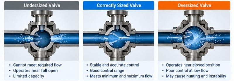
An oversized control valve has substantially more flow capacity than the process requires.
Oversizing is a common problem when a valve is selected primarily by matching the pipeline diameter.
For example, a DN100 pipeline does not automatically require a DN100 control valve.
The appropriate valve size depends on the flow coefficient, pressure drop, velocity limits, noise, and process requirements.
Common Problems Caused by Oversizing
An oversized control valve may operate near the closed position during normal conditions.
This can produce several problems.
First, small valve movements may cause disproportionately large changes in flow.
Second, the available control range may become limited, making accurate regulation more difficult.
Third, the valve may experience frequent movement as the controller attempts to maintain the process setpoint.
In some applications, this behavior can contribute to wear, hunting, and unstable process performance.
Oversizing may also increase actuator requirements or installation costs without improving the process.
How Can Engineers Avoid Oversizing?
The most effective approach is to calculate the required Cv or Kv at minimum, normal, and maximum flow.
The resulting values should then be compared with the manufacturer’s published valve characteristics.
Valve travel, rangeability, actuator performance, and the installed flow characteristic should also be evaluated.
A correctly sized valve should provide sufficient capacity without sacrificing useful control performance.
What Happens When a Control Valve Is Undersized?
An undersized control valve cannot deliver the required flow under the available operating conditions.
This may prevent a process from reaching its intended production capacity.
For example, an undersized valve in a cooling water system may restrict the available cooling flow.
In a steam system, insufficient valve capacity may prevent the process from reaching the required heat input.
An undersized valve may operate near its maximum opening for extended periods, leaving little additional capacity when demand increases.
However, simply increasing the valve size is not always the correct solution.
The engineer should first verify whether the limitation comes from the valve itself, the available pressure differential, or another part of the piping system.
How to Size a Control Valve for Steam and Gas
Control valve sizing for compressible fluids is more complex than simplified liquid sizing.
Steam and gas density changes as pressure and temperature change.
The calculation must account for compressibility and the possibility of choked flow.
For gas applications, important parameters include:
- Inlet and outlet absolute pressure
- Operating temperature
- Gas molecular weight or specific gravity
- Compressibility factor
- Ratio of specific heats
- Required mass or volumetric flow
- Valve pressure recovery and expansion characteristics
For steam applications, engineers must also consider steam quality, thermodynamic state, and operating pressure.
What Is Choked Flow?
Choked flow occurs when reducing downstream pressure no longer produces a corresponding increase in flow through the valve.
For compressible fluids, this is associated with critical flow conditions within the restriction.
For liquids, choking can occur when vapor formation limits the effective flow capacity.
When choked flow is possible, simple sizing equations are insufficient.
The applicable valve sizing methodology must account for the relevant fluid properties and valve-specific coefficients.
Why Is Steam Control Valve Sizing Important?
Steam control valves are used in heating, power generation, industrial processing, and thermal systems.
Incorrect sizing can contribute to unstable temperature control, excessive noise, erosion, and inefficient process operation.
Phileda offers a Pneumatic Diaphragm High Temperature Control Valve for high-temperature process regulation, including steam and heat-transfer applications.
The final valve selection should consider the operating temperature, steam conditions, required flow capacity, trim materials, and actuator configuration.
How Do Cavitation and Flashing Affect Control Valve Selection?
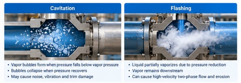
Cavitation and flashing are important considerations in liquid control valve applications.
Both involve vapor formation caused by pressure reduction, but their effects differ.
Cavitation
Cavitation occurs when local liquid pressure falls below vapor pressure, causing vapor bubbles to form.
When pressure subsequently recovers, the bubbles may collapse.
This collapse can produce noise, vibration, and damage to valve trim or nearby components.
High differential pressure applications may require specialized trim designs to reduce cavitation risk.
Flashing
Flashing occurs when liquid partially vaporizes because pressure falls below its vapor pressure and the vapor remains present downstream.
Unlike cavitation, the vapor does not fully collapse after the restriction.
Flashing can produce high-velocity two-phase flow and severe erosion.
Cavitation vs Flashing
| Factor | Cavitation | Flashing |
|---|---|---|
| Vapor formation | Yes | Yes |
| Vapor collapse | Typically occurs during pressure recovery | Vapor persists downstream |
| Main concern | Noise, vibration, localized damage | Erosion and two-phase flow |
| Common design response | Anti-cavitation trim and staged pressure reduction | Suitable geometry, velocity control and erosion-resistant materials |
The final design should use manufacturer-specific pressure recovery data and an appropriate sizing method.
For severe pressure-drop applications, consult the valve manufacturer before confirming the trim design.
How Do Valve Flow Characteristics Affect Sizing?
Control valve flow characteristics describe the relationship between valve travel and flow capacity under defined conditions.
Common characteristics include linear and equal percentage.
Linear Flow Characteristic
A linear valve characteristic produces approximately equal changes in flow coefficient for equal changes in valve travel under a constant pressure differential.
Linear characteristics can be suitable for certain processes where the available pressure drop remains relatively consistent.
Equal Percentage Flow Characteristic
An equal-percentage characteristic produces a similar percentage change in flow coefficient for equal increments of valve travel.
This characteristic is commonly used in processes with varying pressure drop or a wide operating range.
However, the final installed characteristic depends on the interaction between the valve and the piping system.
Which Characteristic Should You Choose?
The selection depends on the process dynamics, available pressure differential, and desired control response.
| Flow Characteristic | Typical Consideration |
|---|---|
| Linear | Systems with relatively stable valve pressure drop |
| Equal percentage | Systems with varying pressure drop or broad operating ranges |
| Quick opening | Primarily associated with on/off service rather than precise throttling |
The appropriate characteristic should be verified through process analysis rather than selected solely from a general recommendation.
How to Choose the Right Control Valve Type
After calculating the required flow coefficient, the next step is selecting the valve construction.
Different valve types provide different advantages in control performance, pressure handling, leakage, and maintenance.
Single Seat Control Valves
Single seat control valves are commonly used when precise throttling and low leakage are important.
Their suitability depends on pressure differential, actuator sizing, trim design, and fluid properties.
Phileda’s HTS Single Seat Pneumatic Control Valve is designed for continuous regulation of flow, pressure, temperature, and liquid level.
Its published product information describes single-seat construction and pneumatic diaphragm or piston actuator options.
Pneumatic High Pressure Control Valves
High-pressure applications require careful evaluation of pressure containment, actuator force, and trim design.
Phileda’s Pneumatic High Pressure Control Valve is intended for industrial processes involving high pressure and pressure differential.
Available design features described by the manufacturer include specialized pressure-reduction structures and selectable flow characteristics.
Electric High Pressure Control Valves
Electric actuation may be appropriate when remote automation is required and an instrument air system is unavailable or undesirable.
Phileda offers an Electric Ultra High Pressure Control Valve for high-pressure automated regulation.
Its published product description identifies configurable control characteristics, sealing arrangements, and electrical protection options.
V Port Control Ball Valves
V port ball valves can be considered for applications requiring rotary control and suitable handling of certain process media.
Phileda’s Pneumatic V Port Control Ball Valve combines a V-shaped ball opening with pneumatic actuation.
The manufacturer describes applications involving industrial flow regulation and selected media containing particles.
The final choice should depend on the actual fluid characteristics, shutoff requirements, control range, and operating pressure differential.
How to Select the Correct Control Valve Actuator
Control valve sizing does not end with selecting the valve body.
The actuator must generate sufficient force or torque to position the valve under the specified operating conditions.
For linear valves, actuator thrust is particularly important.
For rotary valves, actuator torque must be evaluated.
Electric Actuators
Electric actuators use electrical power to move the valve.
They may be suitable for remote automation, digital control integration, and facilities without instrument air infrastructure.
The selection should consider electrical supply, actuator force, operating speed, duty cycle, and required failure behavior.
Pneumatic Actuators
Pneumatic actuators use compressed air to move the valve.
They are common in industrial process control and can be configured for different failure responses.
The selection should consider available instrument air pressure, actuator sizing, positioner requirements, stroke time, and spring-return arrangements.
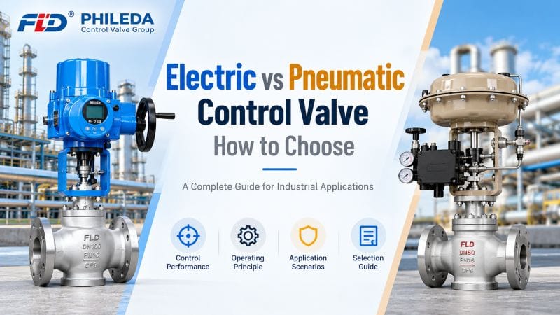
For a detailed comparison, see our guide to Electric vs Pneumatic Control Valve: How to Choose.
What Information Is Required for a Control Valve Sizing Calculation?
A complete technical data sheet is essential for reliable control valve selection.
Before contacting a manufacturer, engineers and buyers should collect the following information.
| Required Information | Purpose |
|---|---|
| Process medium | Identifies fluid properties and compatibility |
| Minimum flow | Evaluates low-load control |
| Normal flow | Establishes typical operating conditions |
| Maximum flow | Confirms required capacity |
| Inlet pressure | Determines upstream conditions |
| Outlet pressure | Determines pressure differential |
| Operating temperature | Supports material and sizing evaluation |
| Density or specific gravity | Required for liquid sizing |
| Vapor pressure | Helps evaluate cavitation and flashing |
| Viscosity | Determines whether viscosity corrections are required |
| Pipe size | Supports installation assessment |
| Required leakage class | Defines shutoff expectations |
| Actuator preference | Supports electric or pneumatic selection |
| Fail-safe position | Defines the required failure response |
| Control signal | Supports PLC/DCS integration |
For steam and gas service, additional thermodynamic data may be required.
The more complete the operating data, the easier it is for the manufacturer to evaluate a suitable valve configuration.
Common Control Valve Sizing Mistakes to Avoid
Several recurring mistakes can affect industrial valve performance.
Selecting the Valve by Pipe Size Alone
Pipe diameter does not determine the required control valve flow coefficient.
The valve must be sized using process flow and pressure conditions.
Using Only Maximum Flow
Maximum flow is important, but minimum and normal flow conditions are equally relevant to control performance.
Ignoring Cavitation and Flashing
A valve may have adequate nominal flow capacity while still being unsuitable for severe pressure-drop conditions.
Confusing Rated Cv With Operating Cv
Rated Cv represents the valve’s capacity at a defined opening, usually full travel.
Operating Cv is the capacity required at a particular process condition.
These values are not interchangeable.
Ignoring Actuator Sizing
A correctly sized valve body may still perform poorly if the actuator cannot generate sufficient thrust or torque.
Failing to Confirm Shutoff Requirements
Control performance and shutoff leakage are different requirements.
Buyers should specify the applicable leakage class and operating conditions.
Why Work With a Control Valve Manufacturer for Final Sizing?
Preliminary calculations are useful for comparing options and preparing procurement documents.
However, final industrial control valve selection often requires more detailed engineering.
A manufacturer can evaluate the required flow coefficient alongside valve geometry, pressure recovery characteristics, trim design, actuator sizing, and material compatibility.
Phileda supplies industrial control valves for applications including chemical processing, power generation, oil and gas, and water treatment.
Its Control Valve product category includes pneumatic control valves, single-seat valves, high-pressure configurations, and other process control products.
For complex operating conditions, buyers should submit their process data and request a technical selection review before confirming the order.
Conclusion
Control valve sizing is essential for stable and reliable industrial process regulation.
The correct selection requires more than matching the valve to the pipeline diameter.
Engineers must evaluate Cv or Kv, flow range, pressure differential, fluid properties, valve characteristics, and actuator requirements.
Oversized valves can produce poor control at low operating flow, while undersized valves may restrict process capacity.
Cavitation, flashing, choked flow, and high-pressure conditions require additional analysis beyond simplified sizing equations.
For industrial buyers, the most effective approach is to prepare complete operating data, perform preliminary sizing, and verify the final valve configuration with the manufacturer.
FAQ
1. What is control valve sizing?
Control valve sizing determines the flow capacity required to regulate a process under specified operating conditions. It considers flow rate, pressure drop, fluid properties, and valve characteristics.
2. How do you calculate Cv for a control valve?
For simplified, non-choked liquid flow, use Cv = Q × √(SG/ΔP), where Q is in US GPM and ΔP is in psi. More complex conditions require additional sizing factors.
3. Can a control valve be smaller than the pipe?
Yes. A control valve may be smaller than the pipeline if its calculated capacity and installation conditions are suitable.
4. What happens if a control valve is oversized?
An oversized valve may operate near the closed position, reducing useful control range and contributing to unstable regulation.
5. What information does a manufacturer need for valve sizing?
Provide fluid type, minimum and maximum flow, operating pressures, temperature, pipe size, shutoff requirements, and actuator preferences.
Request Control Valve Sizing Support From Phileda
Selecting the right control valve requires accurate process data and an understanding of the operating conditions.
Phileda offers industrial control valve solutions for flow, pressure, temperature, and process automation applications.
Whether your project involves liquid flow control, steam regulation, high-pressure service, or automated industrial pipelines, our team can review your requirements and help identify a suitable valve configuration.
Explore our industrial control valve range or contact Phileda to discuss your application and request a technical quotation.