Control valve sizing is one of the most important steps in industrial valve selection. A control valve may have the right body material, actuator, pressure rating, and connection size, but if the sizing is wrong, the system can still suffer from unstable flow, noise, vibration, leakage, poor temperature control, actuator overload, or premature trim wear.
Many valve problems begin with a simple mistake: selecting the valve according to pipe size only. In reality, a control valve should be sized according to actual process conditions, including medium type, flow range, inlet pressure, outlet pressure, temperature, pressure drop, required control range, and shut-off requirements.
This guide explains how control valve sizing works from a practical engineering and procurement perspective. It is written for industrial users who need stable regulation in steam, water, gas, oil, chemical, heat transfer, and process automation systems.
Table of Contents
What Is Control Valve Sizing?
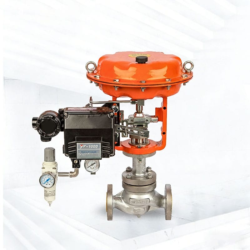
Control valve sizing is the process of selecting a valve with the correct flow capacity for a specific process condition. The goal is to make sure the valve can regulate flow accurately across the required operating range without being too large or too small.
In industrial automation, a control valve works as the final control element in a process loop. It adjusts the valve opening to control flow, pressure, temperature, or liquid level. Correct sizing allows the valve to respond smoothly to control signals and maintain stable process performance.
For buyers comparing different valve options, Phileda’s control valve product range includes pneumatic control valves, electric control valves, self-operated valves, ball valves, butterfly valves, shut-off valves, and other industrial valve solutions for process control applications.
Why Pipe Size Alone Is Not Enough
Pipe size tells you the pipeline diameter. It does not tell you how much flow the valve must control, how much pressure drop is available, or whether the valve can regulate smoothly during normal operation.
A DN100 pipeline does not always need a DN100 control valve. In many systems, the correctly sized control valve may be smaller than the pipeline because the valve is selected by flow capacity rather than pipe diameter.
| Selection Method | Common Result |
|---|---|
| Selecting by pipe size only | High risk of oversizing or unstable control |
| Selecting by maximum flow only | Poor low-flow regulation |
| Selecting by normal flow and pressure drop | Better control performance |
| Selecting by full process data | More reliable long-term operation |
A valve that is too large may operate near the closed position most of the time. This makes small valve movements create large flow changes, causing hunting, vibration, poor control accuracy, and seat wear.
Key Data Required Before Control Valve Sizing
Before sizing a control valve, the project team should collect complete operating data. Incomplete data often leads to inaccurate model selection.
| Required Data | Why It Matters |
| Medium type | Determines sizing method, material, sealing, and corrosion resistance |
| Medium state | Liquid, gas, saturated steam, superheated steam, or mixed phase |
| Minimum flow | Checks whether the valve can control at low demand |
| Normal flow | Main basis for stable daily operation |
| Maximum flow | Confirms peak capacity |
| Inlet pressure | Defines upstream condition |
| Outlet pressure | Defines downstream condition and pressure drop |
| Temperature | Affects density, viscosity, material, packing, and sealing |
| Pipe size | Confirms installation and connection |
| Control purpose | Flow, pressure, temperature, or level control |
| Failure position | Supports process safety logic |
| Leakage requirement | Determines seat and trim design |
For sizing methods and flow equation guidance, the ISA control valve sizing standards committee is a useful technical reference for engineers working with control valve selection.
Understanding Cv in Control Valve Sizing
Cv is one of the most common flow capacity values used in valve sizing. It represents the valve’s ability to pass flow under defined pressure drop conditions. A higher Cv means the valve can pass more flow.
However, buyers should not choose the largest Cv available. The correct Cv should match the actual operating range. If the selected Cv is much larger than required, the valve may be oversized and difficult to control.
| Cv Selection Result | Process Impact |
| Cv too small | Valve cannot deliver required maximum flow |
| Cv too large | Valve may control poorly at small openings |
| Cv close to required range | Better modulation and process stability |
| Cv selected without pressure data | High risk of incorrect sizing |
In practical selection, the manufacturer should check the minimum, normal, and maximum flow conditions rather than using only one design point.
Pressure Drop: The Core of Control Valve Sizing
Pressure drop is the difference between inlet pressure and outlet pressure across the valve. It is one of the most important factors in control valve sizing.
If pressure drop is too low, the valve may not have enough authority to regulate flow effectively. If pressure drop is too high, the valve may face noise, vibration, cavitation, flashing, erosion, or excessive velocity.
| Pressure Drop Condition | Possible Issue |
| Too little pressure drop | Poor controllability |
| Too much pressure drop | Noise, erosion, cavitation, or flashing |
| Unstable pressure drop | Difficult control loop tuning |
| Incorrect pressure data | Wrong valve size or trim selection |
For high-pressure and severe service applications, buyers should provide detailed pressure data. Phileda’s Electric Ultra High Pressure Control Valve may be considered for automated regulation in demanding high-pressure systems where pressure drop and actuator matching require careful review.
Liquid, Gas, and Steam Sizing Are Different
Different media require different sizing considerations. A control valve used for clean water cannot be sized in the same way as a valve used for steam, gas, heat transfer oil, or corrosive chemical fluid.
| Medium Type | Key Sizing Concern |
| Liquid | Viscosity, pressure drop, cavitation, flashing |
| Gas | Compressibility, pressure ratio, noise, velocity |
| Steam | Saturated or superheated condition, pressure drop, temperature |
| Heat transfer oil | Viscosity, temperature, leakage risk |
| Chemical media | Corrosion, density, vapor pressure, material compatibility |
| Hot gas | Velocity, erosion, thermal expansion, noise |
For high-temperature steam, heat transfer oil, and hot gas systems, Phileda’s Pneumatic Diaphragm High Temperature Control Valve can be reviewed when the project requires stable regulation under elevated temperature conditions.
Oversized Control Valve: A Common Hidden Problem
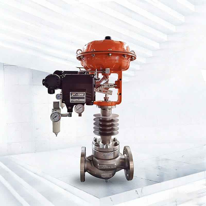
Oversizing is one of the most common control valve sizing mistakes. It often happens when buyers add too much “safety margin” or choose the same valve size as the pipeline without checking real flow conditions.
An oversized valve may appear safe because it can pass enough flow, but it often creates control problems.
| Oversizing Symptom | Possible Cause |
| Valve hunts or oscillates | Valve opening is too small during normal operation |
| Temperature control is unstable | Small travel changes create large flow changes |
| Seat wears quickly | Frequent throttling near closed position |
| Noise occurs at low opening | High velocity through a small opening |
| Positioner works constantly | Control loop is trying to correct unstable flow |
| Process output fluctuates | Valve rangeability is not suitable |
A correctly sized valve should operate within an effective travel range during normal conditions. It should not remain almost closed most of the time.
Undersized Control Valve: When Capacity Is Not Enough
An undersized valve creates a different problem. It may not deliver enough flow when the system reaches peak demand. This can reduce production capacity, slow heating, create pressure loss, or prevent the process from reaching the required operating target.
| Undersizing Symptom | Possible Cause |
| Maximum flow cannot be reached | Valve Cv is too small |
| Downstream pressure is too low | Excessive restriction |
| Heating process is slow | Steam or thermal oil flow is insufficient |
| Pump load increases | System resistance is too high |
| Valve stays fully open | Valve has no control margin left |
A valve that stays fully open during normal operation is no longer controlling effectively. It is only acting as a restriction in the pipeline.
Rangeability and Control Accuracy
Rangeability describes the usable flow control range of a valve. A valve with good rangeability can control both low and high flow conditions more effectively.
This is especially important when the process has wide load variation. For example, steam demand may be low during startup or partial production but much higher during full operation.
| Process Condition | Why Rangeability Matters |
| Wide flow variation | Valve must control both low and high demand |
| Batch production | Flow may change frequently |
| Heat exchanger control | Load may vary with product temperature |
| Utility systems | Demand changes during different operating periods |
| Chemical dosing | Low-flow accuracy may be critical |
Phileda’s HTS Single Seat Pneumatic Control Valve is suitable for continuous control applications involving flow, pressure, temperature, and liquid level when the working conditions match the valve configuration.
Flow Characteristic Selection
Control valve sizing is not complete without choosing the correct flow characteristic. Flow characteristic describes how flow changes as valve travel changes.
The common options are linear, equal percentage, and quick opening.
| Flow Characteristic | Behavior | Typical Application |
| Linear | Flow changes evenly with valve travel | Stable pressure drop systems |
| Equal percentage | Flow change increases gradually as the valve opens | Systems with changing pressure drop |
| Quick opening | Large flow change at small opening | On/off or fast filling service |
Equal percentage is often used in steam, gas, and heat exchanger applications because system pressure drop may change as flow changes. Linear trim may be suitable for systems with more stable pressure drop. Quick opening trim is generally not suitable for precise modulating control.
Valve Body Type and Sizing Relationship
Different valve body types have different flow characteristics, pressure drop behavior, and control performance. The valve body should be selected according to the control duty, not only capacity.
| Valve Type | Sizing and Control Consideration |
| Globe control valve | Strong throttling performance and stable regulation |
| Single-seat control valve | Good control accuracy and shut-off performance |
| V-port ball valve | Combines regulation and shut-off ability |
| Butterfly control valve | Compact choice for larger pipelines and moderate control duty |
| Self-operated valve | Suitable for local pressure regulation without external power |
| Electric control valve | Useful for remote electric automation and PLC/DCS integration |
| Pneumatic control valve | Fast response and common choice for process automation |
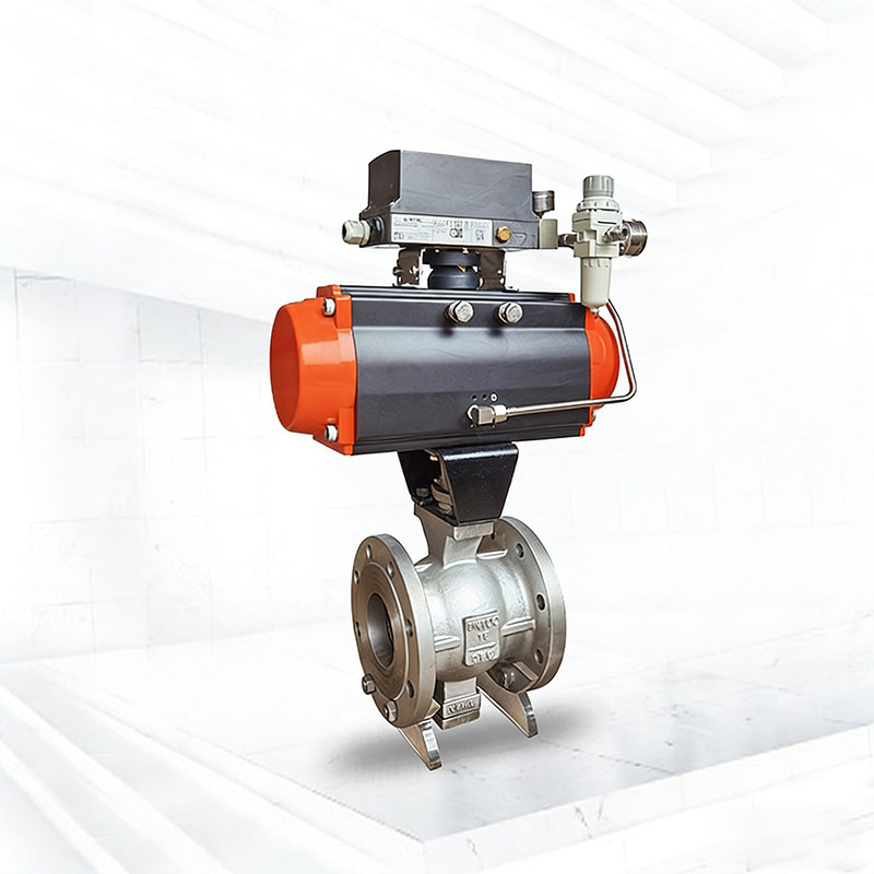
For applications where regulation and shut-off are both required, a Pneumatic V Port Control Ball Valve can be considered when the working conditions match the valve’s flow and sealing requirements.
Actuator Matching After Valve Sizing
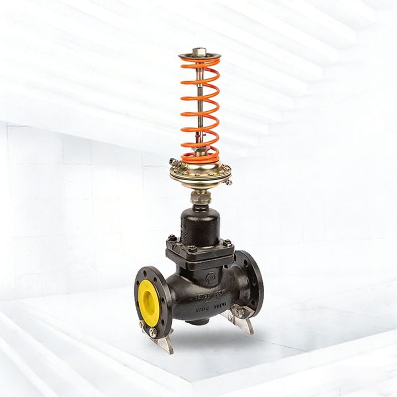
After the valve body is sized, the actuator must be matched correctly. The actuator must provide enough force or torque to move the valve under the maximum pressure differential.
If the actuator is too small, the valve may fail to open, close, or position accurately. If the actuator is not suitable for the control duty, the valve may respond too slowly or fail to maintain stable control.
| Actuator Factor | Why It Matters |
| Required thrust or torque | Must overcome pressure differential and friction |
| Control mode | Modulating control or on/off operation |
| Response speed | Affects process stability |
| Fail-safe position | Important for safety during air or power failure |
| Positioner compatibility | Improves control accuracy |
| Environmental protection | Important for outdoor or hazardous areas |
| Manual override | Useful for commissioning and maintenance |
For many process systems, a pneumatic control valve is selected when fast response and reliable modulation are required. For sites without instrument air, an electric control valve may be more suitable.
Noise, Cavitation, Flashing, and Choked Flow
Control valve sizing must also consider severe service conditions. If the valve experiences high pressure drop, high velocity, or phase change, standard sizing may not be enough.
| Severe Condition | What It Means |
| Cavitation | Vapor bubbles form and collapse in liquid service, damaging trim |
| Flashing | Liquid changes into vapor and remains vapor downstream |
| Choked flow | Flow cannot increase further even if downstream pressure drops |
| High aerodynamic noise | Common in gas and steam pressure reduction |
| High outlet velocity | Can cause vibration, noise, and pipe damage |
| Erosion | Caused by high-speed media or particles |
For liquid service, cavitation can damage valve trim and reduce service life. For steam and gas service, high pressure drop may require special trim or noise control measures.
Material and Trim Selection After Sizing
Sizing determines capacity, but material determines whether the valve can survive the application. A correctly sized valve can still fail if the body, trim, seat, packing, or gasket materials are not suitable.
| Component | Selection Focus |
| Valve body | Pressure, temperature, corrosion resistance |
| Trim | Erosion resistance and control stability |
| Seat | Leakage requirement and media compatibility |
| Packing | Stem sealing and temperature resistance |
| Gasket | Pressure sealing and chemical compatibility |
| Stem | Smooth movement and mechanical strength |
| Actuator bracket | Heat isolation and installation stability |
For general pressure-temperature requirements in industrial valves, ASME B16.34 is a useful reference for valves with flanged, threaded, and welding-end connections.
Common Control Valve Sizing Mistakes
Many control valve problems can be prevented during the selection stage. The most common mistakes include incomplete data, wrong safety margin, and misunderstanding the difference between pipe size and valve capacity.
| Mistake | Possible Result |
| Selecting by pipe size only | Oversized valve and unstable control |
| Using only maximum flow | Poor low-flow performance |
| Ignoring minimum flow | Hunting and poor modulation |
| Not confirming pressure drop | Wrong Cv or noise problems |
| Treating liquid and gas the same | Incorrect sizing result |
| Ignoring temperature | Wrong material or packing selection |
| Forgetting actuator force | Valve cannot move reliably |
| Not checking failure position | Unsafe operation during emergency |
| Ignoring installation layout | Vibration, stress, or maintenance difficulty |
A professional selection should combine sizing calculation, material selection, actuator matching, and installation review.
Control Valve Sizing Checklist for Project Inquiries
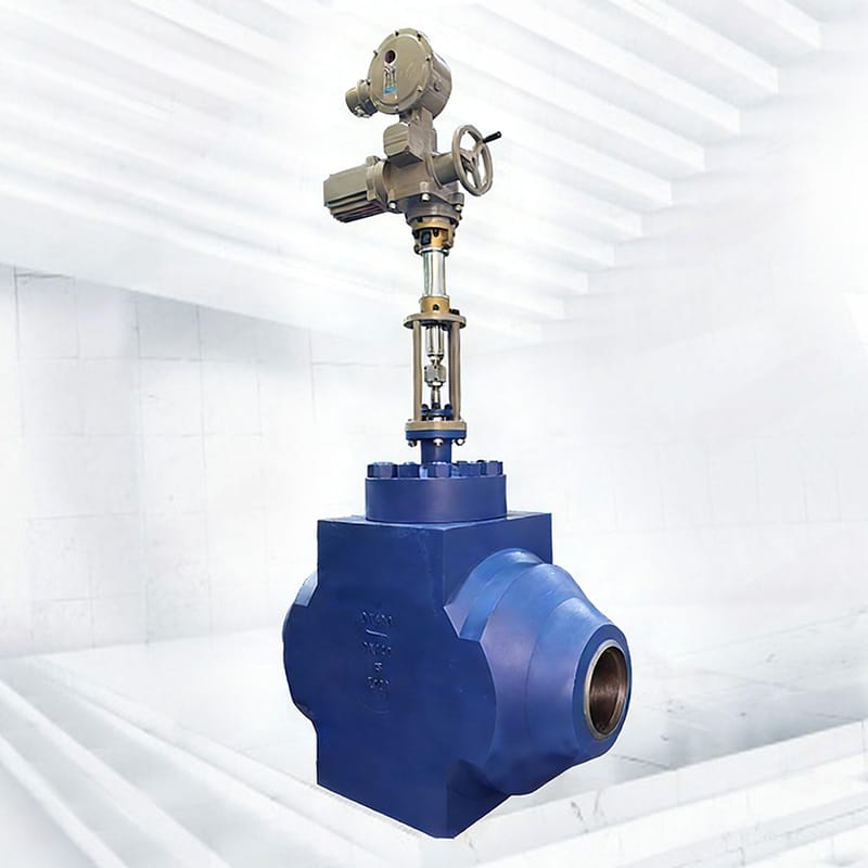
To get an accurate recommendation from a manufacturer, prepare complete process data before requesting a quotation.
| Inquiry Information | What to Provide |
| Medium | Water, steam, air, gas, oil, chemical fluid |
| Medium condition | Liquid, gas, saturated steam, superheated steam |
| Flow rate | Minimum, normal, and maximum |
| Inlet pressure | Normal and maximum upstream pressure |
| Outlet pressure | Required downstream pressure |
| Temperature | Normal and maximum operating temperature |
| Pipe size | DN or NPS |
| Connection type | Flanged, welded, threaded, wafer |
| Control purpose | Flow, pressure, temperature, or level control |
| Valve type preference | Pneumatic, electric, self-operated, ball, butterfly, globe |
| Control signal | 4–20 mA, pneumatic signal, open/close signal |
| Failure position | Fail open, fail closed, or fail in place |
| Material requirement | Carbon steel, stainless steel, alloy, special trim |
| Leakage requirement | Soft seal, metal seal, or specified leakage level |
| Accessories | Positioner, solenoid valve, limit switch, air filter regulator |
For project-specific selection, you can contact Phileda with your process data and control requirements.
Why Work With a Manufacturer for Control Valve Sizing?
Control valve sizing is not just a formula. It requires engineering judgment because real systems often involve fluctuating pressure, changing flow demand, temperature variation, media characteristics, installation restrictions, and control loop requirements.
Working directly with a control valve manufacturer helps project teams confirm valve Cv, body type, trim structure, actuator force, material selection, leakage class, accessory configuration, and documentation requirements.
Phileda provides industrial automatic control valve solutions for steam, gas, water, oil, chemical, heat transfer, high-temperature, high-pressure, and process automation systems. Buyers can review the industrial valve product range or send operating conditions for sizing support.
Conclusion
Control valve sizing directly affects process stability, energy efficiency, equipment protection, and valve service life. A valve selected only by pipe size may be oversized, noisy, unstable, or unable to control accurately. A valve selected only by maximum flow may fail to regulate at normal or low-flow conditions.
A reliable sizing process should consider medium type, flow range, inlet pressure, outlet pressure, pressure drop, temperature, Cv, valve body structure, flow characteristic, actuator force, material compatibility, and installation layout.
For industrial projects involving steam, gas, water, oil, chemical media, high temperature, or high pressure, Phileda can support control valve selection based on actual process data. Review the control valve product range or send your working conditions to confirm the most suitable control valve configuration.