Selecting between an electric and pneumatic control valve is not simply a matter of choosing an actuator. The decision affects control performance, plant utilities, operating safety, maintenance requirements, and long-term reliability.
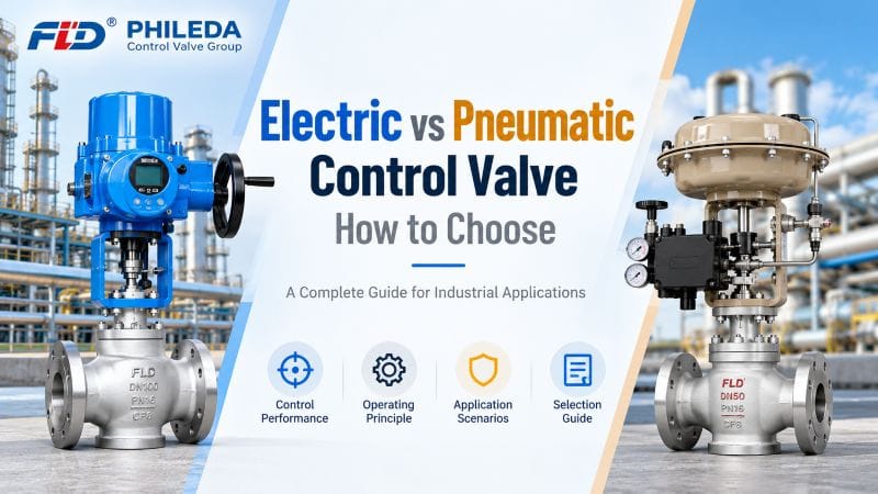
Both technologies are widely used in industrial process automation. Electric control valves use electrical power to position the valve, while pneumatic control valves use compressed air to produce the required movement. Each offers advantages under different operating conditions.
For engineers and industrial buyers, the right choice depends on the process rather than the actuator alone.
This guide compares electric vs pneumatic control valve systems, explains their operating differences, and identifies the factors that matter most when specifying valves for chemical processing, oil and gas, power generation, water treatment, and other industrial applications.
Table of Contents
What Is the Difference Between an Electric and Pneumatic Control Valve?

The main difference between an electric and pneumatic control valve is the source of power used to operate the actuator.
An electric control valve uses an electric motor or another electrically powered actuator to move the valve stem or shaft. A pneumatic control valve uses compressed air acting on a diaphragm or piston.
Both can regulate flow, pressure, temperature, or liquid level when integrated with suitable control equipment.
However, their response characteristics, failure behavior, infrastructure requirements, and maintenance needs can differ significantly.
Electric vs Pneumatic Control Valve Comparison
| Selection Factor | Electric Control Valve | Pneumatic Control Valve |
|---|---|---|
| Power source | Electricity | Compressed air |
| Actuator type | Electric motor-driven | Diaphragm or piston |
| Control signals | Electrical commands through actuator controls | Pneumatic pressure or electrical signals through a positioner |
| Response speed | Depends on motor and gearing | Often fast, depending on air supply and actuator sizing |
| Positioning accuracy | Depends on actuator and feedback system | Depends on positioner and actuator |
| Plant utilities | Electrical supply | Instrument air supply |
| Fail-safe operation | Requires suitable spring, stored energy, or backup arrangement | Commonly achieved with spring-return actuators |
| Maintenance | Motors, gearing, electronics | Air system, seals, diaphragms, positioners |
| Hazardous areas | Requires appropriate equipment certification | Pneumatic actuation can reduce electrical equipment at the valve |
| Typical applications | Remote automation, utility systems, process regulation | Dynamic process control, frequent operation, safety-related duties |
Neither actuator technology is universally superior. The most suitable solution is the one that meets the process requirements with acceptable operating risk and lifecycle cost.

How Does an Electric Control Valve Work?
An electric control valve combines a valve body with an electrically powered actuator.
When the control system sends a command, the actuator converts electrical energy into mechanical movement. This movement changes the valve opening, allowing the system to regulate the process medium.
Depending on the actuator and controller, an electric control valve may support on/off operation, modulating control, position feedback, and communication with a programmable logic controller (PLC) or distributed control system (DCS).
Main Components of an Electric Control Valve
A typical electric control valve assembly includes:
- Valve body and internal trim
- Electric actuator and drive mechanism
- Position feedback device
- Control electronics
- Mechanical coupling or valve stem
- Optional limit switches and protection devices
The valve body determines the flow capacity, pressure containment, and suitability for the process medium. The actuator determines how the valve responds to control commands.
Both components must be selected together.
When Should You Use an Electric Control Valve?
Electric control valves are often suitable for applications where electrical power is readily available but a reliable compressed air system is not.
They can also be useful when the application requires remote position monitoring, programmable operation, or integration with digital automation systems.
Common applications include water treatment, industrial utility networks, automated production equipment, and selected high-pressure process systems.
For example, Phileda offers an Electric Ultra High Pressure Control Valve designed for electrically actuated regulation in demanding high-pressure applications.
The manufacturer’s published information identifies configurations for high-pressure systems and automated operation. However, the final pressure rating, actuator torque or thrust, control performance, and protection functions must be confirmed for the specified operating conditions.
How Does a Pneumatic Control Valve Work?
A pneumatic control valve uses compressed air to generate mechanical force.
Air pressure acts on a diaphragm or piston, producing movement that changes the valve opening. A positioner can compare the required valve position with the actual position and adjust the actuator pressure accordingly.
In modern process control systems, pneumatic valves frequently receive electrical control signals through electro-pneumatic positioners.
This allows pneumatic control valves to operate within PLC and DCS environments without requiring an electric motor at the valve.
Why Are Pneumatic Control Valves Common in Process Industries?
Pneumatic actuators have a long history in continuous industrial process control.
They are particularly useful where plants already maintain instrument air systems and where the valve must respond frequently to changing process conditions.
Properly designed pneumatic systems can offer rapid movement, straightforward mechanical operation, and practical fail-safe configurations.
Typical applications include chemical processing, power generation, oil and gas facilities, and industrial temperature or pressure regulation.
Phileda’s Pneumatic Control Valve is presented for continuous regulation of flow, pressure, temperature, and level in industrial pipelines.
The published product information also describes positioner-based control and configurable actuator arrangements.
Actual response time, positioning accuracy, air consumption, and failure behavior should be verified against the final valve and actuator configuration.
Which Control Valve Provides Better Accuracy?
Control accuracy is one of the most common concerns when comparing electric vs pneumatic control valve systems.
However, actuator type alone does not determine control accuracy.
The complete control assembly must be considered, including the valve trim, actuator, positioner, feedback mechanism, and process control loop.
Factors Affecting Control Accuracy
Valve sizing is critical. An oversized valve may operate close to its seat during normal conditions, making stable regulation more difficult.
Flow characteristics also matter. Linear and equal-percentage characteristics behave differently as the valve opens, and their suitability depends on the installed process conditions.
Other factors include:
- Actuator resolution and repeatability
- Mechanical backlash and friction
- Valve stem or shaft movement
- Positioner calibration
- Process pressure fluctuations
- Controller tuning
- Valve rangeability and installed flow characteristics
A well-designed pneumatic control valve with a properly calibrated positioner can deliver precise control.
Likewise, an electric control valve with suitable feedback and actuator sizing can provide repeatable positioning.
The correct comparison should therefore be based on the required control performance rather than broad claims that one technology is always more accurate.
Electric vs Pneumatic Control Valve Response Speed
Response speed becomes particularly important in processes involving rapid pressure changes, frequent adjustments, or safety-related operations.
Pneumatic actuators can provide fast movement when supported by adequate air supply, correctly sized tubing, and suitable accessories.
Electric actuator speed depends on the motor, gearing, load, and selected operating mode.
However, a faster actuator does not automatically produce better process control.
An actuator that moves too quickly for the process may contribute to oscillation or unstable operation if the control loop is poorly tuned.
What Should Engineers Evaluate?
Instead of comparing actuator technologies based only on nominal operating speed, engineers should evaluate the complete system.
Important considerations include required stroke time, control signal response, valve travel, actuator thrust or torque, and process dynamics.
For safety-related applications, the specified closure time must be assessed together with the required failure response.
A pneumatic spring-return arrangement may be appropriate for certain duties, while an electric actuator with a certified or engineered fail-safe mechanism may be suitable for others.
The choice depends on the required safety function and its verified performance.
Which Control Valve Is Better for High-Pressure Applications?
Both electric and pneumatic control valves can be designed for high-pressure service.
The pressure rating of the valve body and the ability of the actuator to overcome process forces are more important than the power source alone.
High-pressure applications introduce several engineering challenges, including large differential pressure, high actuator force requirements, cavitation, flashing, noise, and erosion.
These conditions must be evaluated during valve sizing and trim selection.
High-Pressure Electric Control Valves
Electric actuators may be selected when the application requires remote automation, precise positioning, or operation without an instrument air system.
For demanding service, actuator thrust and torque must be sufficient to move the valve under the maximum specified differential pressure.
Phileda’s A105 Explosion Proof Electric High Pressure Control Valve T948Y uses an ASTM A105 forged steel body and an electric actuator configuration intended for high-pressure process control.
Its published product description identifies hazardous-area actuator options and compatibility with industrial automation signals.
The applicable explosion-protection certification, pressure rating, temperature limits, and actuator sizing must be confirmed for the individual project.
High-Pressure Pneumatic Control Valves
Pneumatic actuators can also be suitable for high-pressure service when properly sized.
The actuator must generate enough force to overcome the differential pressure acting on the valve trim, packing friction, and other mechanical loads.
For severe applications, the valve may require pressure-balanced trim, specialized materials, or multi-stage pressure reduction.
The final selection should consider both control performance and the risk of mechanical damage caused by excessive pressure drop.
Electric vs Pneumatic Control Valve for Hazardous Areas
Hazardous-area suitability is an important consideration in oil and gas, petrochemical, and certain chemical processing facilities.
Electric actuators installed in classified hazardous areas must have an appropriate explosion-protection design and certification for the installation.
The required protection depends on the applicable regulations, gas or dust classification, temperature class, and equipment protection level.
Pneumatic actuators can reduce the amount of electrical equipment located directly at the valve.
However, a pneumatic control valve assembly may still contain electrical positioners, solenoid valves, switches, or transmitters.
These accessories must also be suitable for the hazardous area.
Therefore, pneumatic operation should not automatically be treated as proof that the complete valve assembly is safe for an explosive atmosphere.
For international projects, buyers should confirm the relevant certification requirements and equipment markings before placing an order.
How to Select a Control Valve for Different Industrial Applications
The selection process should begin with the operating conditions rather than a preferred actuator type.
Different industries place different demands on the valve assembly.

Chemical Processing
Chemical plants may require accurate flow control, corrosion-resistant materials, and reliable operation under varying temperature and pressure conditions.
Pneumatic control valves are frequently used where instrument air is available and process conditions change continuously.
Electric control valves may be suitable for remote operation or systems where pneumatic infrastructure is unavailable.
Material compatibility is particularly important when handling aggressive chemicals.
Oil and Gas
Oil and gas applications may involve high differential pressure, hazardous atmospheres, and strict safety requirements.
The actuator must be selected together with the pressure rating, trim design, and required failure position.
Neither electric nor pneumatic actuation should be selected without considering the applicable project specifications.
Power Generation
Power plants use control valves in steam, feedwater, cooling water, and auxiliary process systems.
The required actuator depends on the process dynamics, operating temperature, pressure conditions, and available plant utilities.
High-temperature and high-pressure service may require specialized valve trim and materials.
Water Treatment
Water treatment facilities frequently use automated valves for distribution, filtration, and flow regulation.
Electric actuators can be practical where electrical power is readily available and centralized instrument air is not.
Pneumatic actuators remain suitable for plants with established compressed air infrastructure or applications requiring frequent operation.
Control Valve Sizing: Why It Matters More Than Actuator Type
Selecting the correct actuator does not compensate for an incorrectly sized control valve.
Valve sizing determines whether the assembly can regulate the required flow over the specified operating range.
For liquid applications, sizing commonly involves the flow coefficient Cv or Kv, pressure differential, liquid density, vapor pressure, and other operating parameters.
Gas and steam applications require additional consideration of compressibility, pressure ratio, temperature, and potential choked flow.
Key Information Required for Valve Sizing
| Parameter | Why It Matters |
|---|---|
| Fluid type | Determines the appropriate sizing method |
| Minimum, normal and maximum flow | Establishes the operating range |
| Inlet pressure | Defines upstream conditions |
| Outlet pressure | Determines pressure differential |
| Operating temperature | Influences materials and sizing |
| Fluid density or specific gravity | Required for flow calculations |
| Vapor pressure | Helps assess cavitation and flashing |
| Pipe diameter | Supports installation and velocity assessment |
| Required shutoff class | Determines leakage requirements |
| Available utilities | Helps select actuator technology |
| Required fail position | Defines safety-related actuator behavior |
For technical sizing guidance, engineers can consult the International Society of Automation (ISA), including the ISA/IEC 60534 series of control valve standards.
These standards provide a recognized framework for industrial control valve terminology, sizing, and performance evaluation.
Common Mistakes When Selecting Electric or Pneumatic Control Valves
One frequent mistake is choosing an actuator based only on the available power source.
Although utility availability matters, it should not outweigh the actual process requirements.
Another mistake is assuming that every electric actuator provides more accurate positioning than a pneumatic actuator.
Control performance depends on the complete valve assembly.
Engineers should also avoid selecting a valve based only on nominal pipe size. The correct valve size must be determined from flow requirements and operating conditions.
Failure behavior is another critical consideration.
An electric valve that remains in its last position during a power outage may be suitable for one process but unacceptable for another.
Similarly, a pneumatic valve that moves to a predetermined position during air failure must be configured according to the process safety requirements.
Finally, buyers should avoid requesting a quotation without sufficient operating data.
Incomplete technical information can lead to unsuitable valve sizing, incorrect actuator selection, and unnecessary revisions during project execution.
What Should Buyers Include in a Control Valve RFQ?
A well-prepared request for quotation helps manufacturers recommend a suitable valve assembly and reduces the risk of technical misunderstandings.
For electric vs pneumatic control valve selection, the RFQ should include the process operating conditions, control requirements, and site utilities.
Control Valve RFQ Checklist
Interactive checklist
0 of 11 items completed Copy checklistFluid type and compositionMinimum, normal and maximum flowInlet and outlet pressureOperating and design temperaturePipe size and connection standardControl characteristic and shutoff classAvailable electrical or instrument air supplyRequired fail-safe positionControl signals and PLC/DCS requirementsHazardous-area classification, if applicableRequired inspection, testing and documentation
For special service conditions, buyers should also provide information about corrosive media, suspended solids, erosion, noise restrictions, and installation limitations.
A complete RFQ allows the valve manufacturer to evaluate the application rather than simply quote a standard product.
Why Work With an Experienced Control Valve Manufacturer?
Industrial control valve selection requires an understanding of fluid dynamics, actuator performance, materials, and process automation.
A manufacturer with engineering capabilities can help evaluate these factors as a complete system.
Phileda Control Valve Group manufactures industrial automatic control valves, including electric control valves, pneumatic control valves, butterfly valves, ball valves, and eccentric rotary valves.
Its published manufacturing capabilities include CNC machining, automated production equipment, testing facilities, and engineering support for project-specific valve requirements.
For industrial buyers, this provides an opportunity to discuss both the valve body and actuator configuration with a single supplier.
Explore Phileda’s industrial control valve product range to review available configurations for different applications.
Conclusion
The electric vs pneumatic control valve decision should be based on process requirements, operating conditions, available utilities, and safety considerations.
Electric control valves are often attractive where electrical infrastructure is available and remote automation is important.
Pneumatic control valves are frequently preferred where instrument air is already installed, fast actuation is required, or a spring-return failure response is desirable.
However, neither technology is inherently the best choice for every industrial application.
Correct valve sizing, actuator selection, material compatibility, and control system integration are essential for reliable performance.
For a new installation or valve replacement project, the most effective approach is to provide the manufacturer with complete operating data and evaluate the proposed valve assembly against the actual process requirements.
FAQ
1. Which is better, an electric or pneumatic control valve?
Neither is universally better. Electric valves are often practical where electricity is available but compressed air is not. Pneumatic valves are commonly used in plants with instrument air systems and frequent control demands.
2. Are pneumatic control valves faster than electric control valves?
They can be, but response speed depends on actuator design, sizing, air supply, motor gearing, and valve load. Compare specified stroke times rather than actuator type alone.
3. Can electric control valves operate in hazardous areas?
Yes, when the actuator and associated electrical equipment have the appropriate explosion-protection design and certification for the installation.
4. Do pneumatic control valves require electricity?
The actuator uses compressed air, but electrical power may still be required for positioners, solenoids, and control equipment.
5. What information is needed to select a control valve?
Provide the process medium, flow range, inlet and outlet pressure, temperature, pipe size, required leakage class, control signal, available utilities, and failure position.
Get Engineering Support for Your Control Valve Project
Choosing between electric and pneumatic control valves requires more than a product comparison. The correct assembly must match the actual process conditions.
Phileda supports industrial buyers with control valve selection, application evaluation, and project-specific configurations.
Whether your project requires a high-pressure electric control valve or a pneumatic valve for continuous process regulation, our engineering team can review your requirements and recommend a suitable solution.
Contact Phileda to discuss your control valve requirements and request a technical quotation.