Choosing the right electric actuated control valve can make or break your industrial automation system. Whether you are handling water treatment, chemical processing, or HVAC applications, the valve you select directly impacts system efficiency, operational costs, and long-term reliability.
This guide walks you through everything you need to know—from how these valves work to sizing, material selection, and what to look for in a manufacturer.
Table of Contents
Introduction
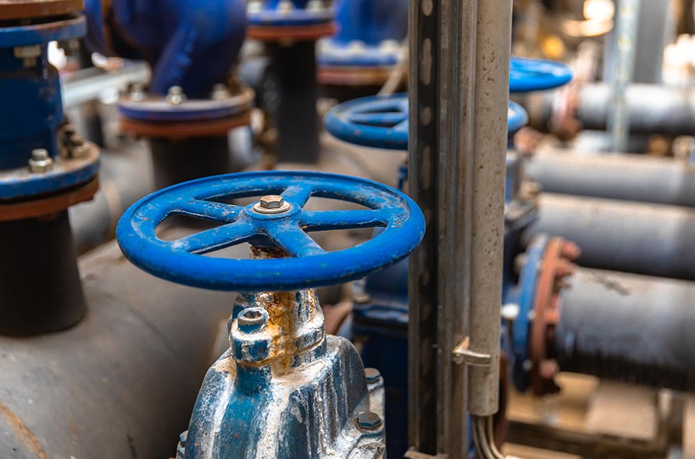
Industrial processes depend on precise flow control. Manual valves cannot provide the accuracy, repeatability, or remote operation capabilities that modern facilities require. Electric actuated control valves bridge this gap, offering automated regulation of fluid flow with minimal human intervention.
For project engineers and procurement specialists, the challenge lies in navigating the technical specifications, balancing performance requirements against budget constraints, and selecting components that integrate seamlessly with existing control infrastructure.
This article draws from years of manufacturing experience to help you make informed decisions when specifying electric actuated control valves for your next project.
What Is an Electric Actuated Control Valve?
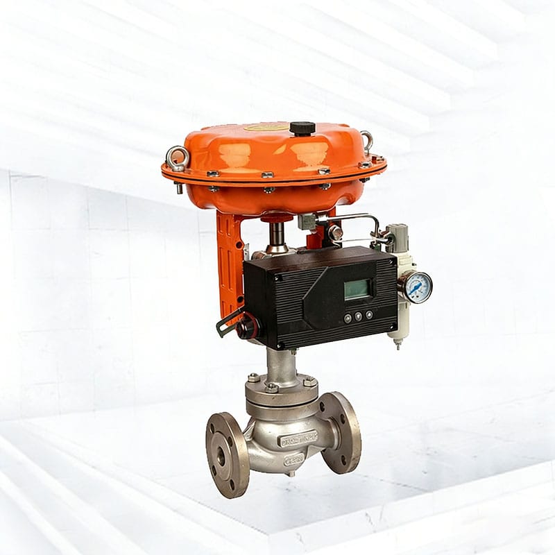
An electric actuated control valve combines a valve body with an electric actuator to regulate fluid flow in response to electronic control signals. Unlike simple on/off valves, these units provide modulating control, allowing precise adjustment of flow rates rather than just open or closed states.
The basic structure consists of two primary components: the valve body, which contains the flow path and throttling element, and the electric actuator, which converts electrical energy into mechanical motion. The actuator receives commands from control systems and positions the valve trim accordingly.
Electric actuators typically use electric motors coupled with gear reduction systems. When power is applied, the motor rotates, and the gears translate this rotation into linear or rotary motion that drives the valve stem. This mechanical movement changes the valve opening position, directly controlling the flow rate through the pipeline.
In automated flow control systems, these valves serve as final control elements. They receive signals from controllers, PLCs, or distributed control systems and adjust positions to maintain desired process parameters such as flow rate, pressure, or temperature.
A critical distinction exists between control valves and standard on/off valves. On/off valves simply alternate between fully open and fully closed positions—useful for isolation but inadequate for regulation. Control valves excel at throttling, maintaining intermediate positions for continuous flow modulation. This capability makes them essential for processes requiring tight tolerance control.
How Electric Actuated Control Valves Work in Industrial Systems
The working principle of electric actuator control revolves around converting electrical commands into precise mechanical positioning. The control system sends an electrical signal to the actuator, which interprets this signal and drives the motor to achieve the target position.
Signal control typically relies on standard industrial protocols. The most common formats include 4–20mA current signals, which offer excellent noise immunity over long distances, and 0–10V voltage signals, which work well for shorter runs. Digital inputs using fieldbus protocols like Modbus, Profibus, or Hart enable more sophisticated communication and diagnostic capabilities.
Operation modes divide into two categories: modulating and on/off. Modulating control continuously adjusts valve position in response to changing process conditions, maintaining precise setpoints. On/off operation simply drives the valve to fully open or fully closed positions based on discrete commands. Many applications benefit from modulating control, while others require rapid cycling between end positions.
Feedback systems provide position verification through potentiometers, encoders, or Hall effect sensors. These devices report actual valve position back to the control system, enabling closed-loop control and confirming that commanded positions have been achieved. Without feedback, the system cannot verify proper operation.
Integration with PLC and automation systems occurs through standard industrial interfaces. Most modern electric actuators support direct connection to PLC analog outputs, with the actuator interpreting the signal and driving to the corresponding position. More advanced setups leverage digital communication protocols for enhanced monitoring, diagnostics, and multi-actuator coordination.
Key Types of Electric Actuated Control Valves
Several valve configurations pair with electric actuators, each suited to specific applications and flow characteristics.
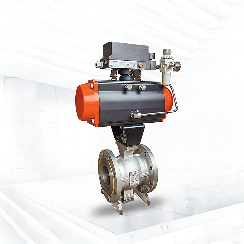
Electric actuated ball control valves use a spherical ball with a bore to control flow. Rotation of the ball aligns the bore with the pipeline for full flow or positions it perpendicular for shutoff. Ball valves offer excellent shutoff capability, low pressure drop in the full-open position, and reliable performance across many applications. They work particularly well for clean media and applications requiring bubble-tight shutoff.
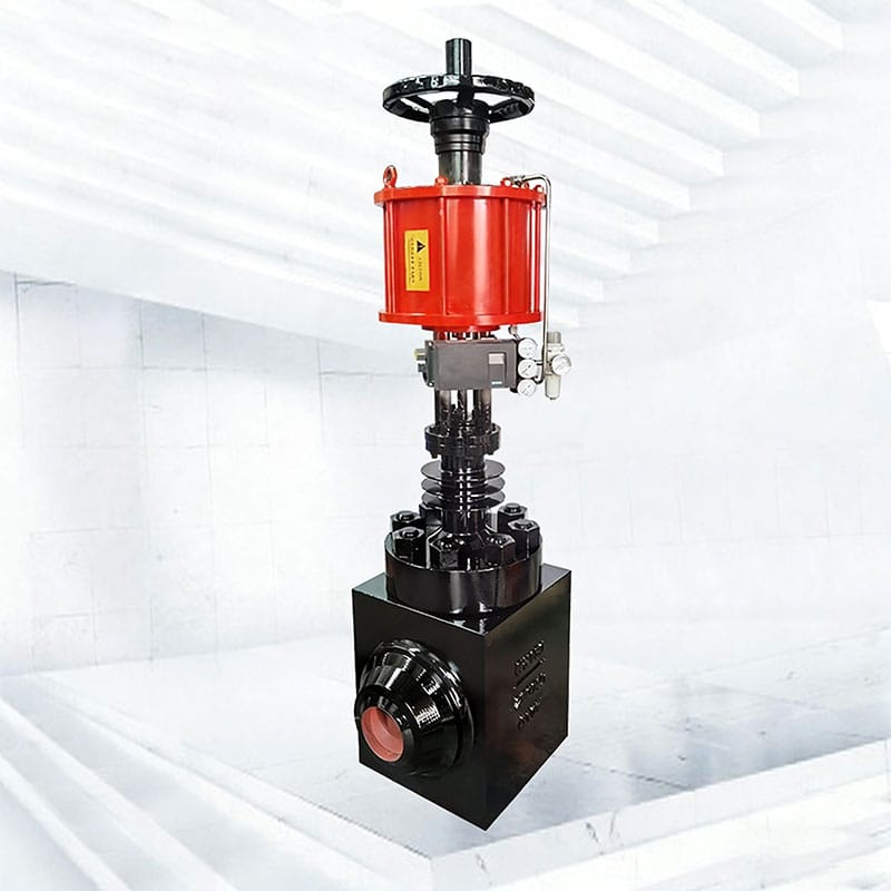
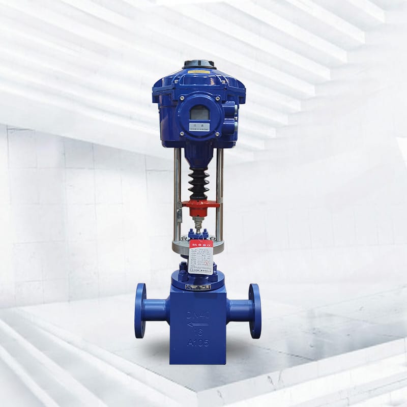
Electric actuated globe control valves employ a movable plug that seats against a ring to throttle flow. The plug travels perpendicular to the flow path, and the degree of opening determines flow rate. Globe valves provide superior throttling accuracy and better control characteristics than ball valves, making them preferred for precision flow control applications.
Electric butterfly control valves use a circular disc that rotates within the flow stream. The disc pivots from fully closed (parallel to flow) to fully open (perpendicular to flow). These valves offer compact design, low weight, and cost-effective sizing for large pipe diameters. Control accuracy is moderate compared to globe valves, but they excel in applications where space and weight matter.
Actuator types further categorize as linear or rotary. Linear actuators produce straight-line motion to drive valve stems directly, ideal for globe valves and other linear-motion designs. Rotary actuators generate rotational motion, suited for ball valves, butterfly valves, and other quarter-turn applications. Your valve selection should align with the required actuator type for optimal performance.
Flow characteristics influence control performance. Equal percentage characteristics provide fine control at low openings with progressive opening at higher positions—suitable for applications with varying pressure drops. Linear characteristics deliver proportional response across the entire stroke, preferred when pressure drop remains constant throughout operation.
How to Select the Right Size and Flow Capacity (Cv Value)
Proper sizing ensures the valve handles your flow requirements without excessive pressure loss or control problems. The Cv value provides the foundation for this selection process.
Cv value represents the flow coefficient—the volume of water in US gallons that passes through the valve in one minute at 60°F with a 1 psi pressure drop across the valve. Higher Cv values indicate greater flow capacity. Every valve size and type has a unique Cv rating at various opening positions.
Calculating flow requirements involves determining the maximum and minimum flow rates your process demands, along with available pressure drop. Using the process fluid properties, design flow rate, and allowable pressure loss, you can apply standard equations to derive the required Cv value.
Oversizing creates significant problems. When the valve operates near the low end of its range, control becomes coarse and imprecise. The excessive capacity forces the valve into restricted positions where flow characteristics degrade. This leads to hunting, instability, and accelerated wear on both the valve and actuator.
Undersizing presents equally serious issues. The valve cannot achieve required flow rates, creating bottlenecks in your process. The actuator works continuously against high differential pressures, leading to premature failure and inability to maintain setpoints.
Pressure drop considerations deserve careful attention. While some pressure loss across the valve is necessary for control authority, excessive drop wastes energy and increases operating costs. Balance the need for control sensitivity against pumping costs when selecting valve size.
Matching valve size with your pipeline system requires consulting manufacturer sizing data. Avoid the temptation to simply match pipe diameter—valve trim size often differs from line size to optimize control performance. Review manufacturer sizing software or consult with technical support for critical applications.
Material Selection for Different Industrial Applications
Valve body material determines compatibility with your process media and operating conditions. Incorrect material selection leads to corrosion, leakage, contamination, or catastrophic failure.
Stainless steel electric actuated control valves handle aggressive media and elevated temperatures. Type 316 stainless offers excellent corrosion resistance for most chemical applications, while 304 stainless provides adequate performance for water and mild chemical service. These valves resist pitting, crevice corrosion, and stress cracking that affect lesser materials.
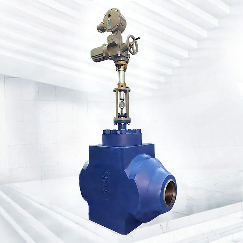
Carbon steel valve applications focus on high-pressure systems and non-corrosive media. Carbon steel handles higher pressure ratings than stainless steel at lower cost. Common uses include steam systems, high-pressure oil applications, and industrial gas handling where corrosion is not a concern.
PVC and corrosion-resistant polymers serve chemical processing and water treatment applications. These materials resist a wide range of corrosive chemicals that would rapidly damage metal valves. Temperature and pressure limitations restrict their use to lower-temperature applications, but the chemical compatibility advantages are substantial for suitable processes.
Chemical compatibility requires systematic evaluation. Review the full chemical composition of your process media, including any additives, impurities, and trace elements. Temperature affects compatibility—materials that resist certain chemicals at room temperature may fail at elevated temperatures. Consult chemical resistance charts and manufacturer recommendations.
Temperature and pressure resistance factors vary by material and valve design. Confirm that selected materials maintain adequate strength and sealing performance across your entire operating temperature range. Pressure ratings typically decrease as temperature increases—ensure your selection provides adequate safety margins.
Electric Actuated Control Valve vs Pneumatic Control Valve
Both electric and pneumatic actuators serve control valve applications, but their characteristics differ substantially. Understanding these differences guides appropriate selection.
| Feature | Electric Actuated Control Valve | Pneumatic Control Valve |
|---|---|---|
| Power Source | Electrical supply (AC/DC) | Compressed air |
| Response Speed | Moderate (typically 5-30 seconds for full stroke) | Fast (typically 1-5 seconds for full stroke) |
| Control Precision | High (±0.5% to ±1% accuracy) | Moderate (±1% to ±2% accuracy) |
| Maintenance Requirements | Lower (brushless motors, sealed gearboxes) | Higher (air filtration, lubricators, seals) |
| Installation Complexity | Moderate (electrical connections required) | Moderate (air lines, filtration, lubricators) |
| Initial Cost | Higher | Lower |
| Operating Cost | Electrical power only | Continuous air consumption |
| Explosion Hazard Suitability | Requires special enclosures | Inherently safe (no electrical sparks) |
| Best Applications | Precision control, remote locations, HVAC | High-speed cycling, hazardous areas, steam |
Energy source comparison highlights a fundamental difference. Electric valves require only electrical connections, simplifying installation in facilities with adequate power distribution. Pneumatic valves need compressed air infrastructure—compressors, dryers, filters, and distribution piping—which adds complexity and ongoing operating costs.
Precision and control accuracy favor electric actuators in most applications. Modern brushless motor control achieves positioning accuracy of ±0.5% or better, while maintaining position without drift. Pneumatic systems struggle with air compressibility, which introduces variability especially at low flow conditions.
Maintenance and operational cost analysis typically favors electric actuators over their service life. Electric actuators have no air consumption, no lubricators to maintain, and no pneumatic seals that degrade. Initial costs are higher, but reduced maintenance offset this disadvantage in many applications.
Best use cases for each type depend on your specific situation. Choose electric actuation for precision modulation, remote locations without air service, or applications where energy efficiency matters. Select pneumatic actuation for high-speed cycling, hazardous areas where spark-free operation is required, or facilities with established compressed air infrastructure.
Common Application Industries for Electric Actuated Control Valves
These valves appear across diverse industries, each with unique requirements and challenges.
Water treatment and wastewater systems rely on modulating control for flow balancing, chemical dosing, and level control. Electric actuators excel here due to their precision, ease of integration with SCADA systems, and ability to operate in outdoor environments with appropriate enclosure ratings.
HVAC and building automation represent major application areas. Control valves regulate chilled water, hot water, and steam flow to maintain comfortable conditions while optimizing energy consumption. Building management systems integrate valve control for centralized monitoring and automatic optimization.
Oil and gas process control demands reliability in challenging environments. Electric actuated valves handle custody transfer measurement, process flow regulation, and safety shutdown functions. Material selection becomes critical given the variety of hydrocarbons and corrosive substances present.
Chemical and pharmaceutical industries require precise flow control for mixing, batch processing, and quality assurance. Material compatibility and cleanability drive material selection, while control accuracy ensures consistent product quality batch after batch.
Power generation and boiler systems use control valves for feedwater regulation, steam conditioning, and cooling water control. High reliability is essential given the continuous operation requirements and safety implications of power generation.
Industrial automation systems integrate electric actuated valves throughout manufacturing processes. From assembly lines to packaging equipment, these valves provide the precise flow control that automated systems require for consistent product quality.
Key Factors That Affect Performance and Reliability
Several factors determine whether your valve performs reliably over years of service or fails prematurely.
Actuator torque selection must account for valve breakaway torque, which is highest when seating or unseating the valve, plus any additional forces from differential pressure. Undersizing the actuator leads to stalled operation, missed positions, and motor damage. Size for at least 30% reserve capacity beyond calculated requirements.
Response time and control accuracy requirements depend on your process dynamics. Slow processes tolerate longer actuator response times, while fast-cycling applications require rapid valve movement. Balance speed against control stability—excessively fast response can cause oscillation and hunting.
IP protection rating indicates resistance to dust and water ingress. Match the enclosure rating to your installation environment. Outdoor installations typically require IP67 or IP68 ratings, while clean indoor environments may tolerate IP54. Higher ratings add cost but prevent premature failure from moisture or contamination.
Duty cycle specifies the percentage of time the actuator can operate without overheating. Standard duty cycles of 25-30% suit intermittent applications, while continuous duty or high-cycle applications require actuators rated accordingly. Exceeding duty cycle ratings causes thermal overload and shortened service life.
Control signal compatibility ensures the actuator works with your existing control infrastructure. Confirm signal types match between your control system outputs and actuator inputs. Some actuators accept multiple signal formats, while others support only specific protocols.
Installation and Commissioning Guidelines
Proper installation prevents most common problems and ensures optimal performance from day one.
Proper mounting orientation matters for actuator longevity. Most actuators prefer vertical or near-vertical mounting to prevent moisture ingress through the shaft opening. Horizontal mounting may be acceptable with additional weather protection. Avoid inverted mounting where water can collect in the actuator housing.
Electrical wiring and control signal setup require careful attention. Follow manufacturer wiring diagrams precisely. Use appropriately sized conductors for the actuator current draw. Shield control signal cables in electrically noisy environments. Ground the actuator properly to prevent electrical noise from affecting control signals.
Calibration of actuator stroke ensures the valve travels its full intended range. Commissioning procedures typically involve commanding the valve to full open and full closed positions, then adjusting limit switches or position feedback to match actual valve travel. Proper calibration prevents over-travel damage and ensures accurate flow control.
System testing before operation verifies correct function throughout the operating range. Cycle the valve through several complete operations while monitoring control signals, feedback signals, and physical movement. Test all control modes and verify that safety interlocks function correctly.
Common installation mistakes include over-tightening mounting bolts (damaging the valve body), incorrect piping orientation (affecting drainage and venting), inadequate pipe support (stressing the valve body), and improper electrical connections (causing erratic operation or damage).
Maintenance and Troubleshooting Tips
Even reliable equipment benefits from systematic maintenance that prevents problems before they affect production.
Routine inspection checklist should include visual examination for damage or corrosion, verification of electrical connections are secure, confirmation that the actuator enclosure remains sealed, and observation of valve movement smoothness during operation. Schedule inspections according to your operating environment—harsh conditions warrant more frequent checks.
Lubrication and mechanical maintenance requirements vary by actuator design. Some actuators feature permanently sealed gearboxes requiring no user maintenance. Others have lubrication points that require periodic greasing. Follow manufacturer schedules and use appropriate lubricants.
Common actuator failures include burnt-out motors from excessive duty cycle or voltage problems, stripped gears from shock loads or inadequate sizing, and failed position sensors causing inaccurate feedback. Most failures announce themselves through slow operation, failure to reach commanded positions, or erratic behavior.
Valve sticking or leakage issues often trace to corrosion between moving parts, foreign material lodged in the seat area, or damaged seating surfaces. Disassemble and clean the valve internals if sticking occurs. Replace seat seals if leakage persists after cleaning. Investigate root causes rather than just addressing symptoms.
Extending service life through preventive maintenance pays dividends. Keep the actuator area clean, verify environmental protection remains adequate, and address minor problems before they cascade into major failures. Document maintenance activities to identify recurring issues and optimize maintenance schedules.
Why Choosing a Reliable Manufacturer Matters
Your valve supplier affects project success far beyond the initial purchase price.
Factory direct sourcing offers significant advantages in quality assurance and cost efficiency. Manufacturers control the entire production process, from casting and machining to assembly and testing. This vertical integration catches quality problems before shipment and eliminates markups from intermediaries.
Quality control in valve manufacturing encompasses multiple dimensions. Material verification ensures correct alloys and heat treatment. Dimensional inspection confirms proper fit and function. Performance testing validates actuation torque, leakage rates, and control accuracy. Request quality documentation and test reports to verify standards are met.
Customization capabilities matter for projects with unique requirements. Standard products may not fit every application—modified connections, special materials, or integrated accessories often prove necessary. A manufacturer capable of sensible customization serves your needs better than one offering only catalog items.
Certification standards provide third-party verification of quality and safety. ISO 9001 certification indicates a functioning quality management system. CE marking demonstrates compliance with European safety directives. Other certifications specific to your industry—such as API for oil and gas or FDA compliance for food and pharmaceutical—validate suitability for specialized applications.
Long-term supply and technical support advantages compound over equipment life cycles. Industrial equipment requires spare parts and service support years after initial purchase. Establish relationships with suppliers capable of supporting products throughout their operational lives, not just until the sale closes.
Cost Factors and Pricing Considerations
Understanding what drives valve costs helps you evaluate quotes and make cost-effective selections.
Raw material costs establish baseline pricing for valve bodies and internal components. Material prices fluctuate with commodity markets—stainless steel, carbon steel, and specialty alloys all respond to global supply and demand. Quality manufacturers source from reputable mills and verify material composition.
Actuator brand and performance level significantly affect total valve cost. Premium actuator manufacturers command higher prices but deliver more reliable performance, better support networks, and longer service lives. Budget actuators may save money initially but cost more through failures and replacements.
Customization versus standard models affects both price and delivery time. Standard products benefit from production efficiencies and inventory availability. Custom configurations require special production runs, engineering time, and often higher reject rates, all adding to cost.
Bulk purchasing advantages become significant for larger projects. Manufacturers offer quantity discounts that improve project economics. Even modest orders of five to ten valves may qualify for better pricing. Discuss volume requirements openly with suppliers.
Total lifecycle cost often matters more than initial price. A cheaper valve that requires frequent maintenance, consumes more energy, or fails prematurely costs more than a higher-quality alternative over its service life. Evaluate options considering all costs—purchase, installation, operation, maintenance, and eventual replacement.
How to Work with a Professional Electric Actuated Control Valve Supplier
Effective supplier relationships improve project outcomes and reduce headaches throughout implementation.
OEM/ODM customization process begins with clear communication of your requirements. Provide detailed specifications including process media, operating conditions, control requirements, connection types, and any applicable standards. Professional suppliers translate these requirements into technical specifications and confirm feasibility before proceeding.
Technical requirement communication works best when both parties share clear documentation. Prepare a specification sheet covering all relevant parameters. Welcome supplier input on areas where your requirements may be unrealistic or where alternative approaches offer advantages. The best outcomes emerge from collaborative specification development.
Sample testing and validation protect against specification mismatches. Request samples for evaluation before committing to full production. Test samples under actual or simulated operating conditions. Use this testing to validate performance and identify any necessary adjustments before production orders.
Production lead time considerations affect project scheduling. Standard products may ship within days, while custom configurations require weeks or months. Build adequate lead time into your project schedule. Understand that rushing production often compromises quality.
After-sales support and warranty policies warrant careful review before purchase. Professional suppliers stand behind their products with meaningful warranties covering manufacturing defects. Evaluate the support infrastructure—technical assistance, spare parts availability, and repair capabilities—to ensure you can get help when needed.
Conclusion
Selecting the best electric actuated control valve for your project requires balancing multiple technical and commercial factors. Focus first on the fundamentals: correct sizing, appropriate materials, and compatible control interfaces. These basics matter more than premium features that may not serve your actual requirements.
Consider the total lifecycle implications of your choice. Initial purchase price represents a small fraction of lifetime operating and maintenance costs. Reliable equipment from quality manufacturers typically delivers better long-term value despite higher upfront costs.
Build relationships with suppliers who understand your industry and can support your specific applications. The right supplier becomes a technical partner, helping optimize specifications and providing ongoing support throughout equipment life.
Whether you need electric actuated ball valves, globe valves, or butterfly valves, ensure the selected solution matches your process requirements, integrates with your control systems, and comes from a manufacturer committed to quality and support.
FAQ
What is an electric actuated control valve?
An electric actuated control valve combines a valve body with an electric motor-driven actuator to regulate fluid flow. It receives control signals (typically 4-20mA or 0-10V) and adjusts valve position to maintain desired flow rates, pressure, or temperature in automated systems.
How does an electric actuator control valve work?
The electric actuator converts electrical energy into mechanical motion through a motor and gear system. When it receives a control signal from a PLC or DCS, it drives the valve stem to the commanded position. Position sensors provide feedback to confirm accurate positioning, enabling precise modulating control.
What are the main advantages of electric over pneumatic control valves?
Electric control valves offer higher positioning accuracy (±0.5% vs ±2%), lower operating costs (no compressed air consumption), easier integration with digital control systems, and suitability for remote locations without air supply. They also require less maintenance since they have no air seals or lubricators.
How do I select the right Cv value for my application?
Calculate required Cv using your maximum flow rate, allowable pressure drop, and fluid properties. The valve should operate between 20-80% of its capacity at normal conditions. Avoid oversizing, which causes poor control at low flows, or undersizing, which creates bottlenecks and excessive pressure loss.
What industries commonly use electric actuated control valves?
These valves serve water treatment, HVAC, oil and gas, chemical processing, pharmaceutical manufacturing, power generation, and general industrial automation. Any application requiring precise, automated flow control benefits from electric actuated valves, especially where integration with modern control systems is needed.