Una válvula puede tener el tamaño correcto y seguir funcionando mal si su actuador no puede mover la moldura a la posición ordenada. La fricción, las fuerzas de presión cambiantes, la carga de empaque, la variación de la presión de suministro y el juego de varillaje pueden separar la salida del controlador del recorrido real de la válvula. Un posicionador de válvula de control cierra ese espacio midiendo la posición de la válvula y corrigiendo la señal del actuador.
La cuestión práctica de la selección no es simplemente si un dispositivo es neumático o digital. Los ingenieros deben hacer coincidir el posicionador de la válvula de control con la arquitectura de la señal, el actuador, la respuesta requerida, la clasificación de áreas peligrosas, el sistema de aire del instrumento, la capacidad de mantenimiento y la importancia del bucle. Elegir únicamente las funciones de comunicación puede producir un dispositivo costoso que es difícil de mantener; elegir sólo por simplicidad inicial puede dejar un bucle crítico sin diagnósticos útiles.
Esta guía proporciona un método de especificación para ingenieros de procesos, equipos de automatización, gerentes de mantenimiento y compradores industriales. Se centra en las decisiones que afectan el control estable y la puesta en marcha confiable, sin asumir que un tipo de posicionador es mejor para cada servicio.
Tabla de contenidos
Qué hace realmente un posicionador de válvula de control
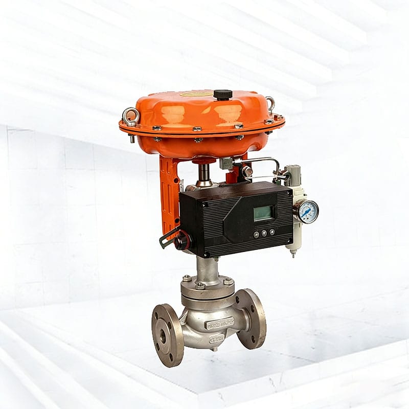
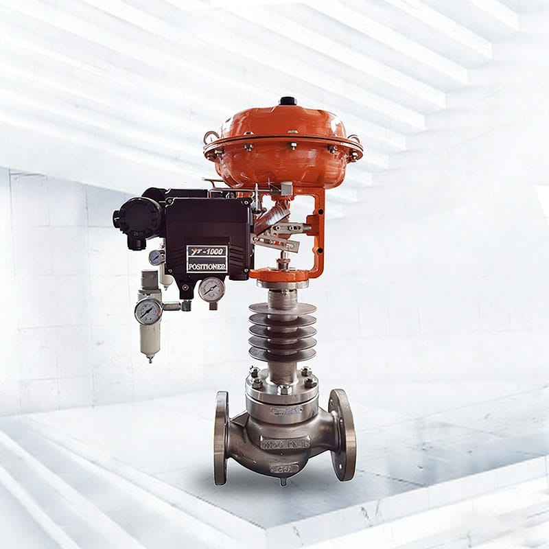
Un posicionador de válvula de control es un controlador de retroalimentación local montado sobre o cerca del actuador. Recibe una señal de comando, detecta la posición del vástago o del eje, compara los dos y ajusta la salida neumática hasta que el recorrido real coincide con el recorrido solicitado. En una válvula lineal, la retroalimentación sigue al movimiento del vástago. En una válvula rotativa, la retroalimentación sigue al ángulo del eje.
Ese bucle local ayuda a superar la fricción del empaque, la fuerza del fluido desequilibrada, la fuerza del resorte del actuador y pequeñas variaciones en la presión de suministro. El posicionador de la válvula de control no reemplaza el tamaño correcto de la válvula ni el ajuste del bucle. Hace que el elemento de control final responda más fielmente a la señal que recibe.
La distinción importa durante la resolución de problemas. Si la salida del controlador cambia pero el recorrido de la válvula no, la causa puede ser fricción, empuje inadecuado del actuador, flujo de aire restringido, un varillaje deficiente o un posicionador de válvula de control configurado incorrectamente. Si el recorrido de la válvula sigue el comando pero la variable del proceso permanece inestable, el problema puede implicar dimensionamiento, dinámica del proceso, detección o ajuste del controlador.
El rendimiento del posicionador de válvulas de control se puede evaluar con métodos definidos en lugar de impresiones de campo subjetivas. El comité ISA75.13 cubre criterios de evaluación y desempeño para posicionadores con entradas y salidas neumáticas, eléctricas u otras.
Cuando sea necesario un posicionador
Un posicionador de válvula de control generalmente se justifica cuando el actuador debe superar una fricción significativa o fuerzas de proceso variables, cuando se requiere un recorrido intermedio preciso o cuando el bucle debe responder rápida y repetidamente. Los casos típicos incluyen cargas de embalaje elevadas, embalaje de grafito, presión diferencial alta, actuadores grandes, control de rango dividido y aplicaciones en las que un pequeño error de viaje cambia la calidad del producto o el uso de energía.
Un posicionador de válvula de control también es valioso cuando el sistema de control es eléctrico pero el actuador es neumático. Un posicionador de válvula de control electroneumático convierte el comando eléctrico en salida neumática manteniendo al mismo tiempo la retroalimentación de posición local. Esta disposición es común en las instalaciones modernas de DCS y PLC porque los actuadores neumáticos proporcionan una gran fuerza y una acción de falla definida mientras la red de control permanece electrónica.
No todas las válvulas necesitan uno. Un servicio simple de encendido y apagado puede requerir sólo una válvula solenoide e interruptores de límite. Un regulador autónomo utiliza presión de proceso en lugar de una señal de control. Para una aceleración no crítica y de baja fricción con líneas de aire cortas, un posicionador puede agregar complejidad sin suficiente beneficio operativo. La decisión debe provenir de la función de control requerida, no de una regla general de la planta.
Posicionadores neumáticos, electroneumáticos y inteligentes
| Tipo posicionador de válvula de control | Entrada típica | Mejor ajuste | Compensación principal |
|---|---|---|---|
| Neumático | Señal de presión neumática | Bucles totalmente neumáticos existentes y control local sencillo | Diagnóstico digital limitado y mayor dependencia del aire limpio de los instrumentos |
| Electroneumático | 4-20 mA | Bucles DCS o PLC convencionales que necesitan un posicionamiento confiable de la válvula | Las versiones básicas proporcionan poca información sobre el estado |
| Digital inteligente | 4-20 mA más comunicación digital | Bucles críticos, mantenimiento predictivo y puesta en marcha remota | Mayores requisitos de configuración y gestión del ciclo de vida |
Un posicionador de válvula de control neumático se adapta a plantas que ya utilizan controladores neumáticos o deben preservar una arquitectura totalmente neumática. Es comprensible para los técnicos familiarizados con boquillas, aletas, relés y señales de presión calibradas. Sus limitaciones son la ausencia de datos digitales enriquecidos y la necesidad de verificar la calidad del aire, la luz, la conexión y el cero mediante rutinas de mantenimiento convencionales.
Un posicionador de válvula de control electroneumático acepta una señal de corriente estándar y produce presión del actuador. A menudo es la opción más directa para un bucle convencional que necesita un posicionamiento confiable pero no una integración avanzada de gestión de activos. El comprador aún debe verificar la impedancia de entrada, la capacidad de salida, la capacidad de rango dividido, el comportamiento de falla y la compatibilidad con el sistema de control.
Un posicionador de válvula de control inteligente agrega un microprocesador, configuración digital, diagnóstico y, a menudo, un protocolo de comunicación. Descripción general de HART del grupo FieldComm explica cómo la información digital puede coexistir con una señal de 4-20 mA. Las funciones inteligentes pueden admitir configuración remota, calibración de viajes, historial de eventos, firmas de válvulas, tendencias de fricción y alertas, pero solo cuando la planta tiene herramientas compatibles, archivos de dispositivos, gobernanza y personal capacitado.
Comience con la arquitectura del sistema y la señal de
El primer elemento de especificación debe ser la señal de comando. Confirme si el bucle proporciona una señal neumática, 4-20 mA, un bus de campo digital o un comando de encendido y apagado. No asuma que “inteligente” significa automáticamente compatible. Un posicionador de válvula de control puede admitir comunicación HART, mientras que la corriente analógica sigue siendo el canal de control principal, mientras que otra arquitectura puede utilizar un bus digital tanto para comando como para diagnóstico.
Compruebe si la tarjeta de salida analógica puede controlar la carga eléctrica, si hay barreras o aisladores y si el dispositivo seleccionado está aprobado para ese bucle. Para tramos de cable largos o áreas peligrosas, verifique el cálculo completo del bucle en lugar de revisar el posicionador de la válvula de control de forma aislada.
Defina la respuesta de falla requerida por separado de la dirección normal de la señal. La pérdida de señal eléctrica, la pérdida de suministro de aire y la falla interna del dispositivo son eventos diferentes. El comportamiento de falla al abrir, cerrar o fallar en el lugar de la válvula depende del diseño del actuador, la disposición del resorte, los accesorios, la energía almacenada y las fuerzas del proceso, así como de la configuración del posicionador de la válvula de control.
Haga coincidir el posicionador con el actuador y la válvula
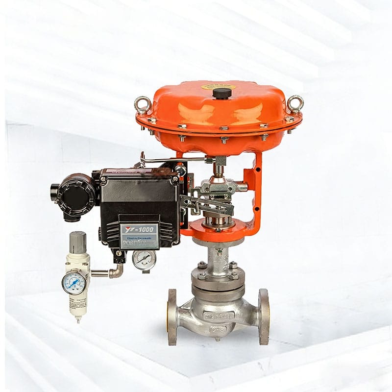
Confirme si el actuador es lineal o giratorio, de acción simple o doble, de retorno por resorte o de aire a la posición. El posicionador de la válvula de control debe proporcionar la disposición de salida correcta y suficiente capacidad neumática para mover el actuador a la velocidad requerida. Un relé de salida pequeño puede hacer que un actuador grande sea lento incluso cuando el posicionamiento en estado estacionario parece aceptable.
El montaje mecánico merece la misma atención. Los soportes, los brazos de retroalimentación, los adaptadores de eje y los rangos de recorrido deben coincidir con el actuador. Una geometría deficiente puede crear no linealidad, pérdida de movimiento o desplazamiento excesivo cerca de los extremos de la carrera. IEC 60534-6-1 aborda los detalles de montaje para fijar posicionadores a actuadores de válvula de control lineal y admite la intercambiabilidad a través de disposiciones de montaje definidas.
Para equipos rotativos, verifique el ángulo de rotación, la dirección, el acoplamiento y los topes de desplazamiento. Para válvulas lineales, verifique el recorrido nominal y la geometría del brazo de retroalimentación. Si el posicionador de la válvula de control se instalará en un actuador existente, obtenga el modelo del actuador, el recorrido, el rango de la mesa y las dimensiones de montaje antes de realizar el pedido.
Evaluar la calidad y capacidad del suministro de aire
El aire del instrumento es parte del sistema posicionador de la válvula de control. El agua, el aceite, el óxido y las partículas pueden restringir pequeños conductos, dañar los relés y cambiar la respuesta. ISO 8573-1 define clases de pureza del aire comprimido para partículas, agua y aceite; la clase requerida debe acordarse para los instrumentos de la planta en lugar de adivinarse a partir de los datos de la placa de identificación del compresor.
Especifique la presión de suministro mínima y máxima en la válvula durante condiciones operativas reales. El posicionador de la válvula de control, el regulador del filtro, los tubos, los accesorios, los propulsores y el actuador deben estar clasificados para la presión máxima. A la presión mínima, el actuador aún debe desarrollar suficiente empuje o torque contra la fuerza del resorte, la fricción del embalaje y la carga del proceso.
La velocidad de respuesta depende de la capacidad de flujo, no de la presión sola. Los tubos largos y estrechos, los accesorios de tamaño insuficiente, los silenciadores bloqueados y los filtros sucios pueden privar al actuador. Si se necesita un refuerzo de volumen o un escape rápido, revise su interacción con el posicionador de la válvula de control. Los ajustes de derivación mal ajustados pueden provocar sobrepasos o ciclos en lugar de un movimiento estable más rápido.
Especifique precisión, banda muerta y respuesta dinámica
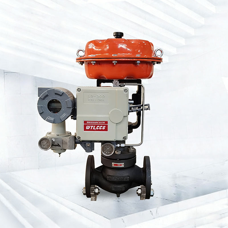
Las hojas de datos utilizan términos como precisión, linealidad, histéresis, sensibilidad, repetibilidad y banda muerta. No describen el mismo comportamiento. Solicite condiciones y definiciones de prueba siempre que el bucle sea crítico. Un posicionador de válvula de control con buena precisión estática aún puede responder lentamente, sobrepasar o luchar contra la fricción de la válvula.
Defina el rendimiento a nivel de válvula ensamblada cuando sea posible. El posicionador, actuador, varillaje, empaque y trimado de la válvula de control funcionan como un elemento de control final. La colección de estándares ISA-75 incluye métodos relacionados con el rendimiento del posicionador, la respuesta de la válvula de control y la estabilidad de la posición, lo que proporciona un marco útil para criterios de aceptación mensurables.
Utilice los requisitos del proceso para establecer el objetivo. Un circuito de temperatura lenta puede no beneficiarse de un recorrido extremadamente rápido, mientras que el reciclaje del compresor, el control de presión o la protección contra sobretensiones pueden exigir una respuesta dinámica cuidadosamente probada. Más rápido no es automáticamente mejor; un posicionador de válvula de control agresivo puede amplificar el juego del varillaje o interactuar mal con un proceso de alta ganancia.
Considere el diagnóstico, la comunicación y el mantenimiento
Los diagnósticos de posicionadores de válvulas de control inteligentes son valiosos cuando conducen a una decisión de mantenimiento. Las funciones útiles pueden incluir desviación de recorrido, presión de suministro de aire, presión de salida, recuento de ciclos, recorrido acumulado, indicadores de fricción, calibración de recorrido, pruebas de carrera parcial y captura de firma de válvula. Antes de especificarlos, decida quién recopilará los datos, dónde se almacenarán y qué límites de alarma activarán la acción.
Un posicionador de válvula de control que admita configuración remota puede reducir el trabajo de campo, pero el control de configuración se vuelve importante. Las plantas deben definir conjuntos de parámetros aprobados, derechos de acceso, prácticas de respaldo, políticas de firmware y procedimientos de reemplazo. Sin esas prácticas, dos dispositivos idénticos pueden comportarse de manera diferente debido a ajustes de ajuste o caracterización no documentados.
Considere también la mantenibilidad local. Los técnicos pueden necesitar una pantalla, botones, puertos de manómetro, terminales extraíbles o una forma sencilla de ventilar la presión de forma segura. La estrategia de repuestos importa: estandarizar una familia de posicionadores de válvulas de control puede reducir la capacitación y el inventario, pero la estandarización no debe anular los requisitos especiales de respuesta rápida, temperatura extrema, saneamiento o servicio peligroso.
Requisitos ambientales y de áreas peligrosas
Para ubicaciones clasificadas, haga coincidir el concepto de protección, el grupo de gas o polvo, la clase de temperatura, el rango ambiental y el método de instalación con la clasificación del sitio. No trate una descripción genérica “a prueba de explosiones” como una especificación completa. El Descripción general del esquema de equipos certificados IECEx explica el papel de la evaluación de la conformidad de los equipos utilizados en atmósferas explosivas.
Revise la protección del gabinete, la resistencia a la corrosión, la vibración, el lavado, la exposición a los rayos UV y la temperatura. Un posicionador de válvula de control montado junto a una tubería caliente puede experimentar una temperatura local más alta de lo que sugieren los datos meteorológicos generales. Puede ser apropiado el montaje remoto, el blindaje térmico, el hardware inoxidable, las placas de circuito recubiertas o un material de gabinete diferente.
Los accesorios deben cumplir con los mismos requisitos ambientales y de áreas peligrosas. Los prensaestopas, solenoides, interruptores de límite, transmisores de retroalimentación, juegos de aire y cajas de conexiones pueden convertirse en el punto débil incluso cuando el posicionador de la válvula de control está correctamente certificado.
Un práctico flujo de trabajo de selección del posicionador de válvula de control
- Defina la función del proceso, el objetivo de control, la acción de falla de la válvula y las consecuencias de un posicionamiento deficiente.
- Confirme la señal de control, la potencia disponible, el protocolo de comunicación, las barreras y la capacidad del sistema host.
- Registre el tipo de válvula, el tipo de actuador, el recorrido o la rotación, el rango de resorte, el empuje o torque requerido y la interfaz de montaje.
- Calcule el rango real de presión de suministro y revise la limpieza del aire del instrumento, la longitud de los tubos y las restricciones de flujo.
- Establecer requisitos de desempeño estáticos y dinámicos mensurables y apropiados para el proceso.
- Decida qué diagnósticos se utilizarán y cómo se gestionarán la configuración, el firmware y los dispositivos de reemplazo.
- Verifique las aprobaciones de áreas peligrosas, los límites ambientales, los materiales del gabinete y el cumplimiento de accesorios.
- Complete una calibración en banco y, para bucles importantes, una prueba de respuesta de válvula ensamblada antes de la puesta en servicio.
Este flujo de trabajo mantiene la decisión del posicionador de la válvula de control conectada al conjunto completo de la válvula y al modelo operativo de la planta. También crea una comparación técnica más clara entre ofertas porque los proveedores responden a la misma tarea en lugar de a una breve descripción genérica.
Qué incluir en una solicitud de cotización de posicionador
Una RFQ útil identifica la etiqueta de la válvula, el servicio, los modelos de válvula y actuador, la acción ante fallas de aire, la señal de comando, la comunicación requerida, la presión de suministro, las conexiones neumáticas, las entradas eléctricas, las condiciones ambientales, la clasificación de áreas peligrosas, los requisitos del gabinete y el estándar de montaje preferido. Incluya medidores, filtros, potenciadores, solenoides, interruptores de límite y transmisores de posición requeridos.
Indique si el posicionador de la válvula de control debe suministrarse suelto, montado y tubular, o montado, calibrado y probado con la válvula. Para un reemplazo, proporcione fotografías e información dimensional, pero no confíe únicamente en fotografías. Es posible que la disposición interna del actuador y la configuración de salida requerida no sean visibles.
Solicite registros de configuración y documentación de prueba adecuada al deber. Para un posicionador de válvula de control crítico, el entregable útil no es una lista larga de características; es evidencia de que la válvula ensamblada se mueve en la dirección correcta, alcanza el recorrido requerido, responde dentro de los límites especificados y adopta el estado de falla requerido.
Errores comunes de selección
- Seleccionar por nombre de protocolo sin comprobar si el sistema host puede configurar y utilizar el diagnóstico.
- Ignorar el volumen del actuador y la capacidad de flujo neumático, y luego intentar corregir el desplazamiento lento solo con el ajuste.
- Suponiendo que el posicionador determina la acción de falla sin revisar las fuerzas del actuador, el resorte, el solenoide y el proceso.
- Solicitar un kit de montaje únicamente a partir del tamaño de la válvula en lugar del modelo del actuador, el recorrido y las dimensiones de la interfaz.
- Especificar la aprobación de áreas peligrosas sin coincidir con la zona, el grupo, la clase de temperatura y el método de cableado exactos.
- Usar aire sucio de la planta y tratar problemas repetidos de relés o boquillas como fallas de calidad del dispositivo.
- Permitir un autoajuste agresivo sin confirmar que el proceso y el ensamblaje mecánico puedan tolerar el resultado.
Evitar estos errores suele ser más valioso que añadir funciones opcionales. Un posicionador de válvula de control bien adaptado con aire limpio, montaje correcto y configuraciones documentadas generalmente superará a una unidad más compleja instalada sin comprobaciones del sistema.
Preguntas frecuentes
¿cada válvula de control necesita un posicionador?
No. Un posicionador de válvula de control es más útil para modular el servicio donde se requiere recorrido preciso, compensación de fricción, conversión de señal o diagnóstico. Las válvulas de encendido y apagado simples, los reguladores autónomos y algunas aplicaciones de limitación de baja demanda pueden utilizar otras disposiciones.
¿cuál es la diferencia entre un convertidor I/P y un posicionador?
Un convertidor I/P transforma una corriente eléctrica en presión neumática. Un posicionador de válvula de control también mide el recorrido real de la válvula y corrige su salida hasta que el recorrido coincide con el comando. Algunos posicionadores electroneumáticos combinan ambas funciones en un solo recinto.
¿puede un posicionador inteligente mejorar una válvula de mal tamaño?
Puede mejorar la precisión del recorrido y ayudar a diagnosticar problemas de fricción o respuesta, pero no puede corregir la capacidad excesiva de la válvula, una característica de flujo inadecuada, cavitación o fuerza inadecuada del actuador. Revisar el guía de dimensionamiento de válvulas de control cuando la capacidad o los viajes operativos son la preocupación subyacente.
¿cómo se debe seleccionar un posicionador para un actuador neumático?
Haga coincidir el posicionador de la válvula de control con el movimiento lineal o giratorio, la salida de acción simple o doble, el volumen del actuador, el recorrido, la presión de suministro, la acción de falla, la interfaz de montaje, la señal de control y la clasificación ambiental. Luego verifique la respuesta ensamblada bajo carga realista.
¿cuándo vale la pena especificar los diagnósticos inteligentes?
Son más valiosos en válvulas críticas, de difícil acceso, de ciclo alto o de mantenimiento cuando la planta tiene una forma práctica de recopilar y actuar sobre los datos. Para conocer el contexto más amplio de selección de válvulas, consulte el guía de selección de válvulas de control neumático y la guía para cavitación versus tapajuntas.
Conclusión
El posicionador de válvula de control adecuado es el que se adapta a todo el sistema de control: señal, actuador, mecánica de válvula, suministro de aire, dinámica de procesos, entorno, recursos de mantenimiento y comportamiento de falla requerido. Comience con el trabajo y el rendimiento mensurable, luego seleccione el nivel de tecnología que la planta puede operar y mantener.
Si está especificando una nueva válvula moduladora o reemplazando un posicionador existente, comparta las condiciones de servicio, los datos de la válvula, los detalles del actuador, la arquitectura de la señal, los requisitos de áreas peligrosas y la respuesta esperada con nuestro equipo de ingeniería. Revisión disponible válvula de control neumático, válvula de control compacta de un solo asiento, y válvula de control neumático monoplaza opciones, o contacta con Fileda para una revisión de configuración basada en su aplicación.