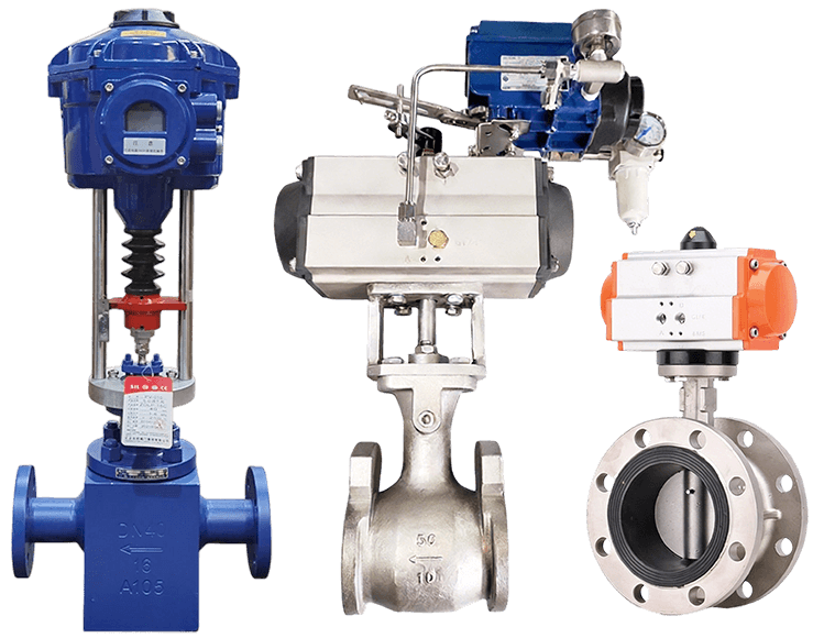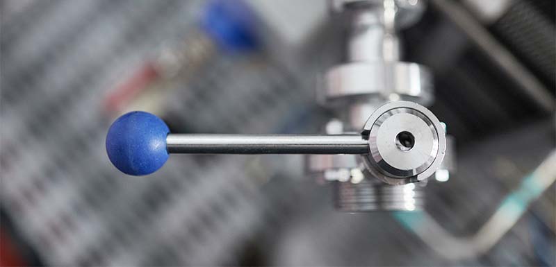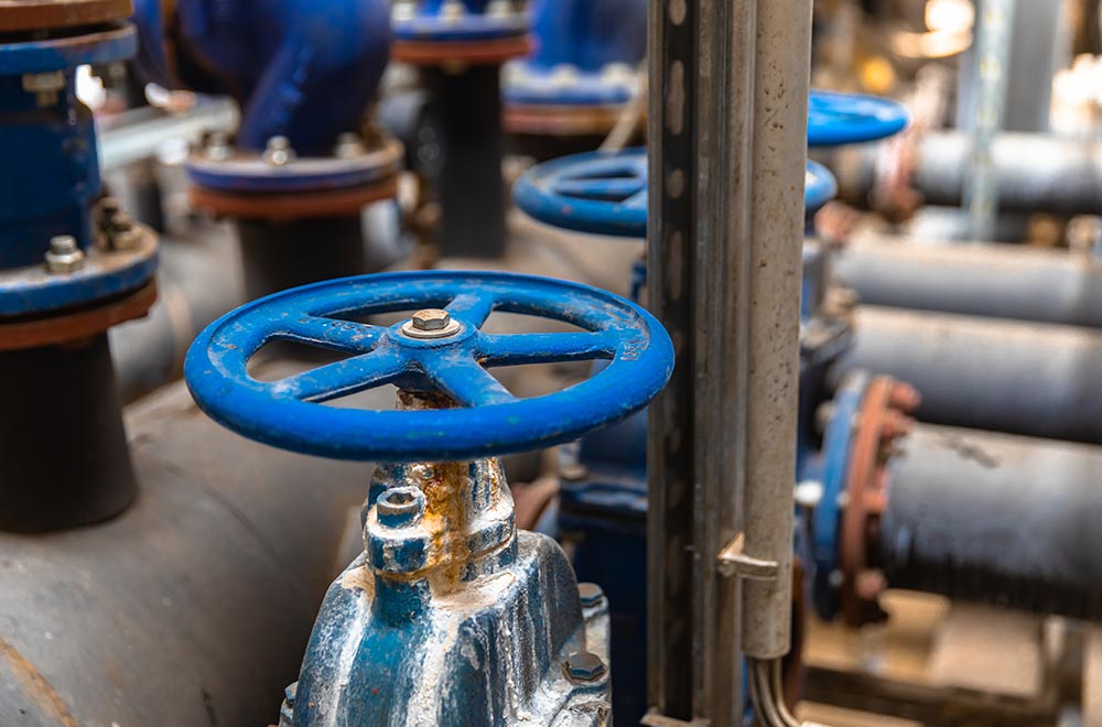
A noisy control valve is rarely just an acoustic inconvenience. The sound may indicate excessive velocity, choked gas flow, cavitation, unstable throttling, mechanical vibration, or a pressure drop being dissipated in the wrong place.
The first step in control valve noise reduction is therefore not choosing thicker insulation or a different actuator. It is identifying the energy source, transmission path, and operating condition that produces the noise.
Gas and steam services commonly generate aerodynamic noise through turbulence and high-velocity jets. Liquid services can produce hydrodynamic noise through turbulence, cavitation, or flashing. Mechanical problems—including loose components, unstable valve position, and piping resonance—can amplify either condition.
This guide explains how to distinguish these mechanisms, collect useful field data, compare noise-control options, and specify a quieter valve without shifting the problem into the downstream piping.
Table des matières
Pourquoi le bruit des vannes de régulation est plus qu'un problème sonore
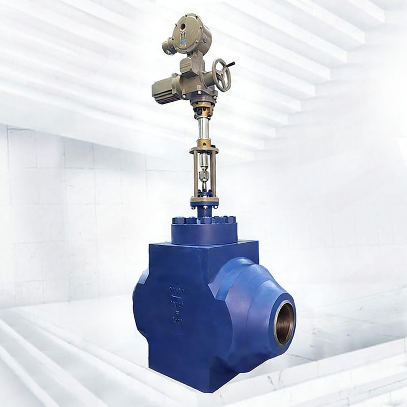
A control valve dissipates process energy by reducing pressure. Under mild conditions, that energy becomes ordinary turbulence and heat. Under severe conditions, it can create powerful gas jets, shock-related turbulence, vapor bubbles, structural vibration, and fluctuating forces on the trim.
These conditions can produce consequences beyond an uncomfortable sound level:
- Trim, seat, cage, stem, shaft, or body damage
- Downstream pipe vibration and fatigue
- Packing leakage caused by repeated movement
- Instrument tubing or supports loosening
- Unstable valve position and poor process control
- Communication difficulties near operating equipment
- Increased worker noise exposure
- Unexpected shutdowns and shorter maintenance intervals
Occupational exposure requirements depend on jurisdiction, exposure duration, frequency spectrum, and work practices. Facilities operating in the United States can consult the OSHA occupational noise resources, while international projects should apply the relevant local safety requirements.
The important engineering distinction is that an acceptable workplace reading does not prove that the valve is operating safely. Internal acoustic energy and vibration can still be high enough to damage trim or piping. Conversely, a mechanically healthy valve may radiate enough airborne sound to require acoustic treatment.
A proper control valve noise review should therefore examine reliability, process performance, piping integrity, and personnel exposure together.
Quatre sources de bruit des vannes de régulation
Most noisy installations involve one or more of four mechanisms.
| Noise mechanism | Typical service | Primary source | Common clues | Main engineering response |
|---|---|---|---|---|
| Aerodynamic noise | Gas, steam, or vapor | High-velocity turbulent jets and compressible-flow effects | Strong hiss or roar that increases with pressure drop or flow | Reduce jet energy, stage the pressure drop, manage outlet velocity |
| Hydrodynamic turbulence | Liquide monophasé | Turbulence and fluctuating pressure | Broad rushing sound without clear cavitation damage | Improve sizing and control velocity |
| Cavitation or flashing | Liquid near its vapor-pressure boundary | Bubble formation, collapse, or persistent two-phase flow | Crackling, vibration, pitting, or downstream erosion | Distinguish cavitation from flashing and change the pressure profile |
| Mechanical vibration | Any medium | Loose components, unstable trim, actuator hunting, or resonance | Rattle, knocking, tonal vibration, or changing sound with valve movement | Inspect components, stabilize control, and evaluate structural resonance |
Sound alone cannot provide a final diagnosis. A hiss may be normal aerodynamic turbulence or severe compressible-flow noise. A rattling sound may indicate cavitation, a loose component, or piping resonance. The sound pattern must be compared with pressure, temperature, flow, travel, and inspection evidence.
Bruit de la vanne de régulation aérodynamique dans le service de gaz et de vapeur
Aerodynamic noise is produced when gas or vapor accelerates through the valve restriction. As pressure decreases, the fluid expands and velocity rises. High-velocity jets mix with slower downstream fluid, creating turbulent pressure fluctuations that generate sound inside the pipe.
When the pressure ratio becomes sufficiently severe, the flow may become choked. Opening the valve farther or reducing downstream pressure may no longer increase mass flow in the expected way, but the additional energy can still increase velocity, noise, vibration, and downstream stress.
Why pressure ratio matters
The differential pressure alone does not describe a compressible-flow case. Inlet pressure, outlet pressure, pressure ratio, gas properties, temperature, molecular weight, specific-heat ratio, compressibility, valve geometry, and flow rate all affect the result.
A valve reducing pressure from a very high inlet condition can produce substantial control valve noise even when its nominal pipe size and Cv appear adequate.
How aerodynamic noise is predicted
Le IEC 60534-8-3 aerodynamic noise prediction method establishes a method for predicting external sound-pressure levels generated by control valves handling single-phase dry gas or vapor. The ISA aerodynamic noise prediction standard also addresses compressible-fluid noise prediction.
A manufacturer’s calculation should use valve-specific data rather than a generic online velocity rule. Relevant factors can include:
- Valve style and rated flow coefficient
- Pressure-recovery characteristics
- Valve opening at each operating case
- Number, shape, and distribution of trim flow passages
- Outlet size and downstream pipe diameter
- Pipe wall thickness and material
- Gas properties and temperature
- Reducers or expanders near the valve
- Required measurement distance and acoustic environment
Prediction results are estimates based on defined assumptions. The actual installation may differ because of nearby elbows, branch connections, pipe supports, insulation, reflecting surfaces, background equipment, and process variability.
Hydrodynamic Control Valve Noise in Liquid Service
Liquid-flow noise begins with turbulence as the fluid passes through the restriction. If the minimum local pressure stays above the liquid’s vapor pressure, the flow remains single phase. The valve may still generate noise, but the mechanism is different from cavitation.
When the minimum pressure falls below vapor pressure, vapor bubbles form. What happens after pressure recovery determines whether the liquid is cavitating or flashing.
Cavitation
During cavitation, downstream pressure recovers above vapor pressure. The bubbles collapse, creating localized shock loads, vibration, noise, and crater-like material damage. Severe cavitation can attack the trim, body, outlet region, or nearby piping.
Clignotant
During flashing, downstream pressure remains at or below vapor pressure. Vapor persists after the valve instead of collapsing. The two-phase mixture can create high outlet velocity, directional erosion, vibration, and sustained noise extending into the downstream piping.
Le IEC 60534-8-4 hydrodynamic noise prediction method covers noise generated by liquid flow, including normal turbulence and cavitation. Laboratory measurement procedures for hydrodynamic valve noise and cavitation onset are addressed by IEC 60534-8-2.
This distinction is essential because low-noise trim designed to control cavitation cannot automatically eliminate flashing. If vapor remains downstream, the engineering solution must manage two-phase velocity, erosion, outlet geometry, and downstream piping.
For a detailed explanation of the pressure conditions involved, review the control valve cavitation and flashing guide.
Mechanical Noise and Vibration
Not all control valve noise originates from fluid dynamics. Mechanical looseness, unstable positioning, structural resonance, or incorrect assembly can create rattling, knocking, humming, or tonal vibration.
Common mechanical causes include:
- Worn plug, cage, shaft, bearing, or guide surfaces
- Loose actuator or yoke connections
- Excessive stem or shaft clearance
- Incorrect flow direction
- A valve operating too close to the seat
- Actuator thrust or torque that is too low
- Positioner tuning that causes hunting
- Instrument-air restrictions or unstable air supply
- Pipe strain that distorts the valve body
- Poorly placed or insufficient pipe supports
- A natural piping frequency excited by flow pulsation
- Reducers, elbows, or branches positioned too close to the valve outlet
Mechanical noise often changes when the valve position, control mode, actuator pressure, or pipe support condition changes. A narrow-frequency hum or repeated knocking may be more consistent with resonance or unstable movement than ordinary turbulent noise.
Do not assume that replacing the valve body will solve these problems. The control loop, actuator, accessories, installation, and piping structure must be inspected as a system.
How Control Valve Noise Reaches the Surrounding Area
A useful noise-control model separates the problem into three parts:
- Source: Where acoustic energy is generated
- Path: How the energy travels through fluid, metal, insulation, supports, or air
- Receiver: The person, instrument, structure, or neighboring equipment affected
Noise generated inside a valve travels through the downstream fluid and excites the pipe wall. The pipe then radiates airborne sound. Vibration may also travel through the valve body, flanges, supports, and connected equipment.
This explains why the loudest external location may be several pipe diameters downstream rather than directly beside the valve. It also explains why adding insulation around the body alone may produce little improvement.
Sound power and sound pressure are different
Sound power describes the acoustic energy generated by the source. Sound-pressure level describes the sound measured at a particular location. The measured value changes with distance, background noise, reflective surfaces, insulation, pipe configuration, and measurement method.
A purchase specification should therefore define:
- Required prediction method
- Operating case being evaluated
- Measurement location and distance
- Whether the limit applies to the valve only or the valve-and-piping system
- Pipe diameter, schedule, and material
- Insulation condition
- Whether the stated value is predicted, tested, or field-measured
- Frequency-weighting and reporting method
Without these details, two suppliers may report different values even when evaluating similar equipment.
An Eight-Step Diagnostic Workflow
A structured investigation is more effective than installing one noise-control device after another.
1. Confirm the operating case
Record minimum, normal, and maximum flow with their corresponding inlet pressure, outlet pressure, and temperature. Include startup, shutdown, bypass operation, cleaning, and upset conditions.
Do not combine unrelated maximum values unless they occur at the same time.
2. Synchronize the data
Trend valve command, actual travel, process flow, P1, P2, temperature, actuator pressure, and noise or vibration measurements on the same time axis.
This helps determine whether control valve noise begins at a specific valve opening, flow rate, pressure ratio, or control-loop event.
3. Verify instruments and pressure basis
Check transmitter ranges, calibration, impulse lines, units, and whether pressures are gauge or absolute. For liquid service, confirm the vapor pressure at the actual fluid temperature and composition.
4. Classify the medium and flow regime
Determine whether the service is:
- Single-phase gas or vapor
- Liquide monophasé
- Liquide cavitant
- Liquide clignotant
- Mixed-phase inlet flow
- Liquid containing solids
- Gas containing droplets or particles
A noise calculation based on the wrong phase model can produce a misleading result.
5. Inspect valve travel and stability
Determine whether the valve operates through a useful travel range or remains near closed. Look for hunting, stick-slip movement, overshoot, or delayed response.
A large valve throttling at very low travel can create a concentrated jet and unstable forces even when its rated Cv is much greater than the required Cv.
6. Map sound and vibration
Measure at repeatable points along the body and downstream piping. Note measurement distance, valve position, process condition, insulation, and nearby equipment status.
Frequency analysis can help distinguish broadband fluid noise from tonal mechanical vibration, although it should be performed by qualified personnel using suitable instruments.
7. Inspect internal and downstream damage
During an outage, examine the trim, seat, guides, body outlet, reducer, downstream pipe, and first elbow. Map pitting, polished erosion, fretting, looseness, and wall thinning.
8. Recalculate the installed valve
Recheck capacity, travel, velocity, choked flow, cavitation, flashing, noise, actuator margin, and fitting effects. Phileda’s guide de dimensionnement de la vanne de commande explains the process information needed for a complete sizing review.
Why Correct Cv Does Not Guarantee a Quiet Valve
Cv indicates flow capacity under defined conditions. It does not independently verify noise, velocity, controllability, cavitation, flashing, vibration, or actuator stability.
Several sizing errors regularly contribute to excessive control valve noise.
Oversizing
An oversized valve may spend most of its operating life close to the seat. Small movements then create large changes in flow area, reducing control resolution and producing a narrow, high-energy jet.
Oversizing can also increase hunting because the valve moves repeatedly around a small opening to maintain the process setpoint.
Sizing only the maximum-flow case
The maximum-flow case determines whether sufficient capacity is available, but the minimum-flow case can be more difficult for controllability and noise. Startup or depressurization may create the most severe pressure ratio even when the flow rate is not at its maximum.
Selecting by line size
The pipeline diameter is not automatically the correct valve size. A properly sized control valve may be smaller than the line, provided reducers, outlet velocity, pressure recovery, and downstream noise are evaluated.
Ignoring installed fittings
Reducers, expanders, elbows, silencers, and diffusers affect flow behavior and acoustic transmission. A calculation based on an isolated valve can differ from the installed result.
Using one noise value for every operating condition
Control valve noise changes with flow, pressure ratio, valve opening, medium properties, and pipe configuration. One predicted value at the design point cannot represent the complete operating envelope.
The Control Valve Noise Reduction Hierarchy
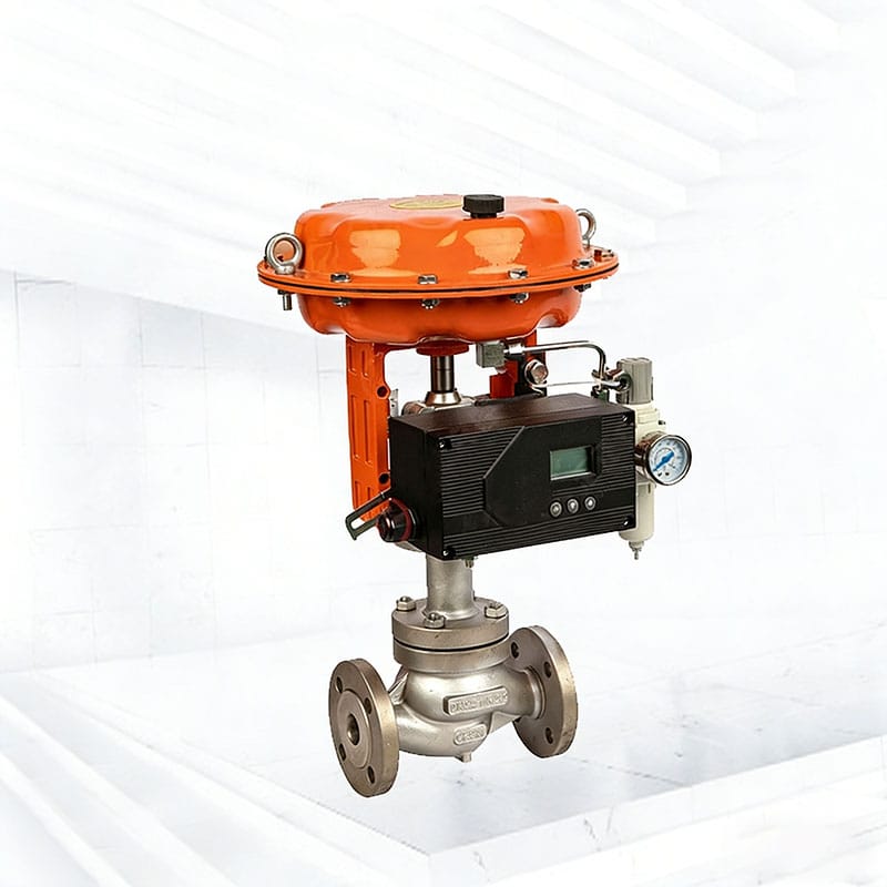
The most reliable mitigation plan begins at the source and moves outward.
1. Reduce unnecessary pressure drop
If process design permits, reduce inlet pressure, increase downstream pressure, relocate the valve, or avoid placing the full system pressure reduction across one device.
Any process change must be reviewed for pump operation, compressor performance, relief scenarios, production capacity, and control authority.
2. Divide the pressure drop
Multi-stage trim or a coordinated valve-and-diffuser arrangement divides one severe pressure reduction into several smaller reductions. This lowers the energy handled by each jet and can reduce peak velocity and acoustic efficiency.
The design must still account for particles, plugging, erosion, and maintenance access.
3. Divide the flow into smaller jets
Low-noise trim commonly uses many carefully distributed passages instead of one large opening. Smaller jets reduce the energy concentrated at a single location and encourage controlled mixing.
The number of stages and passages should be selected using the real operating envelope, not simply requested as a generic “low-noise cage.”
4. Manage outlet velocity
An enlarged outlet, expanded-body construction, properly sized downstream pipe, or engineered diffuser may reduce downstream velocity. The design must avoid creating excessive backpressure or moving the noise source to an unprotected restriction.
5. Treat the transmission path
Pipe-wall thickness, acoustic insulation, silencers, enclosures, and improved supports can reduce radiated or transmitted noise. These measures are useful when source control cannot achieve the entire target.
6. Protect the receiver
Restricted access, remote operation, exposure-time control, and personal protective equipment may be required under the facility’s safety program. These controls do not correct damaging valve conditions and should not replace engineering measures.
Selecting Low-Noise Trim
Low-noise trim is not a single design. The appropriate structure depends on whether the service involves gas, steam, liquid turbulence, cavitation, flashing, clean fluid, or solids.
Multi-hole trim
Multiple small openings divide the total flow into smaller jets. The arrangement can reduce jet interaction and distribute energy more evenly.
Small passages require a careful check of contamination, particle size, fouling, and cleanability.
Multi-stage trim
Several pressure-reduction stages limit the pressure drop across each stage. In gas service, this can reduce jet velocity and aerodynamic noise. In liquid service, staged trim may help keep local pressure above vapor pressure or reduce cavitation intensity.
A pneumatic high-pressure control valve can provide a starting point for high-differential-pressure pneumatic applications. The final trim must still be engineered from the process data.
Tortuous-path trim
A controlled, multi-turn flow path dissipates energy gradually. It may provide strong control valve noise reduction in clean severe-service applications, but narrow paths can be unsuitable for dirty fluids or larger particles.
Guided single-seat trim
A well-guided plug can improve stability where fluctuating fluid forces would otherwise cause vibration. For moderate pressure drops and precise regulation, a compact single-seat control valve may be considered after capacity, noise, stability, and shutoff requirements are checked.
Rotary control trim
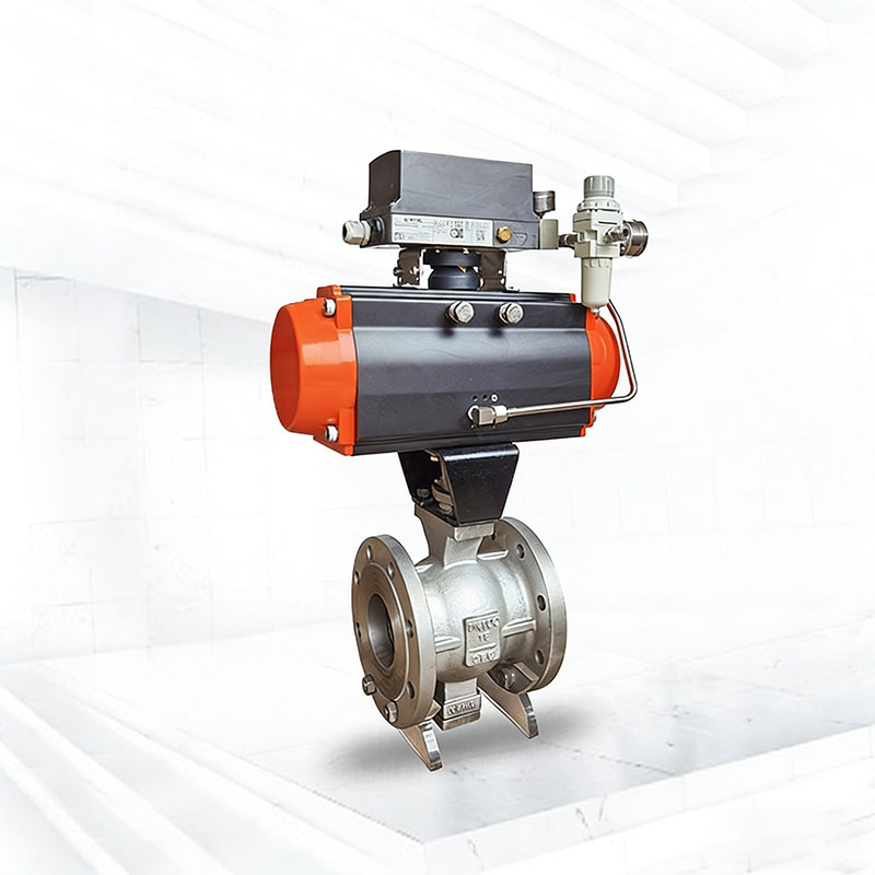
Rotary valves can offer high capacity and a compact structure, but their pressure-recovery and noise behavior must be evaluated at the actual travel. A vanne à bille pneumatique de commande à port en V may suit some modulating services, but a nominal V-shaped opening does not automatically make every application quiet.
Valve architecture should follow the process conditions. Buyers can compare the available control valve product category after defining the flow regime and required noise performance.
Valve Trim, Diffuser, Silencer, or Insulation?
Different treatments act on different parts of the noise problem.
| Solution | Fonction principale | Suitable situations | Important limitations |
| Multi-stage low-noise trim | Reduces noise at the source by distributing pressure drop | Severe clean gas, steam, or liquid pressure reduction | Can require small passages and careful cleanliness control |
| Multi-hole trim | Divides flow into smaller jets | Moderate-to-severe aerodynamic or hydrodynamic noise | Must verify jet interaction, erosion, and plugging risk |
| Downstream diffuser | Shares pressure reduction and controls expansion | Gas or steam systems with suitable downstream space | Creates additional restriction and requires system-level sizing |
| In-line silencer | Attenuates downstream aerodynamic noise | Gas or steam lines where source reduction is insufficient | Adds pressure loss, size, weight, and maintenance requirements |
| Expanded outlet or larger downstream pipe | Reduces velocity and pipe-generated noise | High outlet-volume gas, steam, or flashing service | Does not correct an unsuitable internal pressure profile |
| Acoustic pipe insulation | Reduces airborne sound radiated through the pipe wall | Residual radiated noise after flow conditions are addressed | Does not eliminate internal vibration, cavitation, or erosion |
| Acoustic enclosure | Isolates airborne sound from the surrounding area | Accessible installations with ventilation and maintenance provisions | Must consider heat, leakage detection, access, and actuator operation |
| Improved pipe supports | Reduces movement and structural amplification | Piping vibration or resonance | Poorly designed restraints can transfer forces elsewhere |
The strongest result often combines source treatment with path treatment. For example, low-noise trim may reduce generated sound, while downstream pipe insulation controls the remaining radiated noise.
Piping Decisions That Affect Control Valve Noise
A valve should not be evaluated separately from its piping.
Downstream pipe diameter
Gas and steam expand as pressure falls. If the downstream pipe is too small, velocity and pipe-wall excitation may remain high even after low-noise trim is installed.
Reducers and expanders
Abrupt area changes can create separation, turbulence, and additional noise. Reducer geometry and distance from the valve should be included in the installed calculation.
Elbows and branch connections
A high-velocity jet striking a nearby elbow or branch can cause vibration and localized erosion. Where practical, provide a suitable straight run after the valve based on the engineered arrangement.
Pipe wall thickness
A heavier pipe wall can reduce acoustic transmission in some applications. It should be selected through stress, corrosion allowance, acoustic, weight, and support calculations—not treated as a universal cure.
Pipe supports
Supports should control movement without creating excessive local stress. If vibration is present, review support stiffness, spacing, thermal expansion, and structural natural frequencies.
Insulation
Acoustic insulation must be designed for the required frequency range and installation environment. Thermal insulation alone may not deliver the expected acoustic performance.
Insulation should also allow safe inspection, drainage, leak detection, and maintenance.
Common Noise-Control Fixes That Fail
“Install a larger valve”
A larger body does not guarantee lower control valve noise. It may push normal operation closer to the seat and create poorer control resolution.
Recalculate travel, outlet velocity, pressure recovery, and noise before increasing valve size.
“Add insulation around the valve”
Insulation may reduce radiated airborne sound. It cannot eliminate cavitation, flashing, excessive internal velocity, unstable trim, or structural vibration.
“Replace pneumatic actuation with electric actuation”
The actuator type does not usually remove fluid-generated noise. A different actuator may improve positioning in a specific application, but the valve pressure drop and flow path remain the primary acoustic source.
For unattended high-pressure duties where electric actuation is required, an electric ultra-high-pressure control valve still needs a complete noise and sizing review.
“Use a harder material”
Hard trim can resist erosion. It does not significantly reduce the acoustic energy generated by a high-velocity jet or bubble collapse.
“Specify a maximum dB value without conditions”
A sound limit without the operating case, measurement distance, piping data, and prediction method is incomplete. The supplier cannot reliably determine what configuration must meet the target.
“Use a downstream restriction to create backpressure”
A diffuser or restriction can be part of an engineered solution. An uncalculated orifice may simply become a second noise source, reduce capacity, or create an unsafe pressure condition.
Information Required for a Noise Review
A complete RFQ should allow the valve engineer to calculate capacity, travel, flow regime, velocity, noise, materials, and actuator margin together.
| Groupe de données | Informations à fournir |
| Moyen | Gas, steam, vapor, liquid, composition, solids, droplets, corrosive properties |
| Flow properties | Molecular weight, density, viscosity, specific-heat ratio, compressibility, vapor pressure, critical pressure where applicable |
| Cas opératoires | Minimum, normal, maximum, startup, shutdown, and upset flow |
| Pressures | Corresponding P1 and P2 for every case, clearly marked as gauge or absolute |
| Température | Actual temperature for each operating case |
| Tuyauterie | Upstream and downstream size, schedule, material, reducers, elbows, branches, and available straight run |
| Droit de soupape | Control objective, required Cv, expected travel, rangeability, shutoff class, flow direction, and duty cycle |
| Actionnement | Pneumatic or electric, supply, signal, fail position, stroking time, and accessories |
| Noise requirement | Maximum sound-pressure level, measurement distance, method, insulation condition, and operating case |
| Site evidence | Existing measurements, frequency spectrum, vibration data, photographs, damage history, and previous valve datasheet |
| Project requirements | Materials, pressure class, connections, hazardous-area requirements, testing, documentation, and applicable standards |
If complete process-property data are unavailable, identify the missing values rather than replacing them with unrelated assumptions.
Commissioning a Low-Noise Control Valve
Noise reduction should be verified after installation.
Establish a baseline
Record the process condition, flow, P1, P2, temperature, valve command, actual travel, actuator pressure, sound level, and vibration at defined locations.
Test several operating points
Check minimum, normal, and maximum stable flow where the process permits. A valve may be quiet at design flow but unstable near minimum travel.
Confirm valve response
Verify that the valve reaches commanded positions smoothly and that the positioner is not hunting. Inspect the instrument-air supply, tubing, filter regulator, booster, and actuator settings.
celle de Phileda pneumatic control valve selection guide provides additional guidance on actuator and accessory selection.
Inspect the piping
Check supports, reducers, insulation, bolts, impulse lines, and downstream fittings for movement or looseness.
Preserve comparable records
Future measurements should use the same locations and similar process conditions. A rising sound or vibration trend may provide an early warning before leakage or control failure becomes visible.
FAQ
What causes control valve noise?
Control valve noise can be generated by high-velocity gas or steam, turbulent liquid flow, cavitation, flashing, unstable trim movement, loose components, actuator hunting, or piping resonance. The operating data and damage pattern should be used to identify the actual mechanism.
How do you reduce control valve noise?
Start by reducing noise at the source. Possible measures include correcting valve sizing, reducing unnecessary pressure drop, using multi-stage or multi-hole trim, controlling outlet velocity, improving valve stability, and dividing pressure reduction between engineered devices. Insulation or silencers can then treat remaining transmitted noise.
What is a low-noise control valve?
A low-noise control valve uses a body and trim configuration designed to control how process energy is dissipated. It may use multiple stages, multiple small flow passages, a tortuous path, an expanded outlet, or a coordinated downstream diffuser. The design must be selected for the specific medium and operating cases.
Can an oversized valve cause noise?
Yes. An oversized valve may operate near closed, where a small opening creates a concentrated high-velocity jet. It may also produce poor control resolution and hunting. However, oversizing is only one possible cause, so the installed valve should be recalculated before replacement.
Is control valve noise always caused by cavitation?
No. Cavitation applies to liquid service when vapor bubbles form and then collapse after pressure recovery. Gas turbulence, steam expansion, flashing, mechanical vibration, and ordinary liquid turbulence can also generate significant noise.
Does pipe insulation reduce control valve noise?
Acoustic insulation can reduce sound radiated through the pipe wall, but it does not correct the internal source. Cavitation, excessive velocity, erosion, or mechanical vibration can continue beneath an apparently quieter installation.
Can a silencer be installed after a control valve?
An in-line silencer may be suitable for some gas or steam applications. It must be sized with the valve and piping because it creates pressure loss, changes the system pressure distribution, and may introduce maintenance, drainage, or structural requirements.
What standard is used for control valve noise prediction?
IEC 60534-8-3 addresses aerodynamic noise prediction for compressible fluids, while IEC 60534-8-4 addresses hydrodynamic noise from liquid flow. The project should specify the required standard, operating conditions, and measurement basis.
Why is the downstream pipe sometimes louder than the valve?
Acoustic energy generated at the valve travels downstream through the fluid and excites the pipe wall. The pipe may radiate the highest external sound at a location where internal energy, wall properties, supports, and acoustic transmission combine.
What data should I send for control valve noise calculation?
Provide the medium and properties, minimum/normal/maximum flow, corresponding inlet and outlet pressures, temperature, pipe details, required valve travel and shutoff, actuator data, noise limit, measurement conditions, and any existing noise or vibration measurements.
Conclusion
Effective control valve noise reduction starts with diagnosis, not insulation. Determine whether the source is aerodynamic turbulence, hydrodynamic flow, cavitation, flashing, mechanical movement, or structural resonance. Then connect the noise to the operating case using synchronized pressure, temperature, flow, travel, and vibration data.
Apply solutions in a clear order: remove unnecessary pressure drop, divide severe pressure reduction, control jet formation, manage outlet velocity, stabilize the valve and piping, and treat the remaining transmission path. This approach reduces noise while also protecting trim, downstream piping, process stability, and maintenance reliability.
Pour un examen spécifique à une application, contactez Phileda with the process and piping data listed above. A complete dataset allows the valve, trim, actuator, downstream system, and acoustic target to be evaluated as one engineered solution.