Control valve rangeability appears simple on a datasheet: a ratio such as 50:1 or 100:1 suggests how widely a valve can vary flow while maintaining control. In practice, however, that published value rarely describes the complete installed system.
The catalog ratio is normally determined under controlled conditions with a constant differential pressure across the valve. An operating plant behaves differently. Pump curves, downstream equipment, piping resistance, fluid properties, actuator resolution, valve friction, process gain, and changing pressure drop all influence the minimum and maximum flow that can actually be controlled.
This distinction explains why a valve with apparently high control valve rangeability may still hunt near its seat, produce excessive noise, respond poorly at low load, or fail to reach the required maximum flow.
A reliable selection should therefore evaluate three connected questions:
- What rangeability can the valve trim provide under defined test conditions?
- What turndown can the complete valve assembly achieve?
- What controllable flow range will remain after installation in the real process?
This guide explains the differences and provides a practical method for selecting a valve across minimum, normal, and maximum operating conditions.
Table of Contents
What Is Control Valve Rangeability?
Control valve rangeability is the ratio between the maximum and minimum controllable flow coefficients over which the valve follows its stated inherent flow characteristic within defined limits.
A simplified expression is:
Rangeability = Maximum controllable Cv ÷ Minimum controllable Cv
If a valve has a maximum controllable Cv of 100 and a minimum controllable Cv of 1, its theoretical rangeability is 100:1.
The important word is “controllable.” Flow below the stated minimum may still pass through the valve, but the relationship between travel and flow may no longer be repeatable or stable enough for regulation.
Control valve rangeability should also not be interpreted as the ratio between fully open flow and seat leakage. Leakage is measured under shutoff conditions and belongs to a different performance requirement.
The recognized framework for stating inherent flow characteristics and rangeability is provided by IEC 60534-2-4. The standard applies to industrial-process control valves and establishes how inherent characteristics and rangeabilities are stated and evaluated. The related ISA 75.11 committee scope also addresses inherent flow characterization, rangeability, and allowable deviation from stated curves.
Control Valve Rangeability vs Turndown Ratio
Rangeability and turndown are related, but they should not be used interchangeably.
| Term | What it describes | Pressure conditions | Main limitation |
| Inherent rangeability | Capability of the valve and trim | Differential pressure held constant | Does not represent the complete installed system |
| Assembly turndown | Usable modulation of valve, actuator, and positioner | Defined operating conditions | Limited by resolution, friction, calibration, and stability |
| Installed controllable range | Maximum-to-minimum controllable process flow | Real system pressure changes | Influenced by piping, equipment, process gain, and control-loop behavior |
| Shutoff ratio | Comparison involving closed-valve leakage | Valve closed against stated pressure | Not a control valve rangeability value |
A valve may have high inherent control valve rangeability but lower installed turndown because it never operates fully open, differential pressure changes substantially, or the actuator cannot position the trim accurately at very small openings.
For procurement, the better question is not simply “What is the valve’s rangeability?” It is:
Can this valve assembly control the specified minimum and maximum flows under their corresponding pressure and temperature conditions?
Inherent vs Installed Flow Characteristics
An inherent flow characteristic describes how Cv changes with valve travel while the pressure drop across the valve remains constant.
Common characteristics include:
Linear characteristic
With a linear characteristic, equal increments of valve travel produce approximately equal increments of Cv under constant differential pressure.
Linear trim may suit systems where the valve pressure drop remains relatively stable. Once installed in a system with changing pressure losses, however, the actual flow response may no longer appear linear.
Equal-percentage characteristic
With an equal-percentage characteristic, equal increments of travel produce approximately equal percentage changes in Cv.
The smaller Cv changes near the closed position can support finer low-flow adjustment, while larger changes near full travel provide capacity. This characteristic is often considered for applications with substantial load variation or changing valve pressure drop.
Quick-opening characteristic
A quick-opening valve delivers a large portion of its capacity during the initial travel. It is generally more suitable for on-off or relief-type duties than precise throttling across a broad operating range.
The ISA explanation of control valve flow characteristics notes that inherent characteristics are established with constant pressure drop, while changing valve pressure drop produces a different installed characteristic.
This means two valves with similar published control valve rangeability can behave very differently after installation.
Why Installed Rangeability Is Usually Lower
Several practical limits reduce the flow range available to the control loop.
The valve does not use its full travel
A valve may be sized so generously that normal maximum flow occurs at only 55% travel. The remaining stroke contributes to the catalog control valve rangeability but provides no useful capacity in that installation.
Differential pressure changes with flow
At low system flow, a large portion of available pump or supply pressure may appear across the valve. At high flow, piping and equipment losses increase, leaving less pressure drop across the valve.
Because flow depends on both Cv and differential pressure, the relationship between travel and actual flow changes across the load range.
Low-travel friction becomes significant
Packing friction, seal friction, stem or shaft forces, seat load, and mechanical clearance can represent a large portion of the available movement near the closed position. The result may be stick-slip motion rather than smooth modulation.
Leakage becomes significant relative to demand
A valve may meet its shutoff class while still passing a leakage quantity that is material compared with the required minimum process flow. Low-flow control should therefore compare minimum demand with both minimum controllable flow and permissible leakage.
Instrument resolution is insufficient
The controller, signal converter, positioner, actuator, feedback device, and linkage each contribute to the smallest repeatable movement. A finely characterized trim cannot provide useful control if the complete assembly cannot position it consistently.
How Valve Authority Affects Control
Valve authority describes the relationship between pressure drop across the control valve and the pressure drop across the rest of the controlled circuit.
A simplified expression is:
Valve authority = ΔP across the fully open valve ÷ total circuit ΔP
Low authority means the pressure drop across other system components dominates. As flow changes, the valve’s share of the total pressure drop changes substantially, distorting the installed characteristic.
Higher authority can improve the valve’s ability to influence flow, but it is not free. Additional valve pressure drop may increase pumping or compression requirements and can intensify noise, cavitation, flashing, or energy consumption.
The correct target therefore depends on the process. A project should balance:
- Required control stability
- Available system pressure
- Pump or compressor energy
- Maximum flow capacity
- Noise limits
- Cavitation or flashing risk
- Valve size and travel
- Process response
Control valve rangeability should never be evaluated without considering how the available differential pressure is distributed across the installed system.
Why Oversizing Damages Low-Flow Control
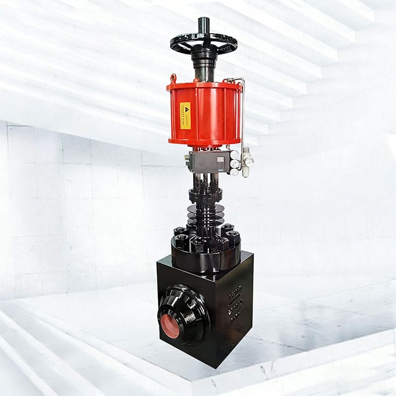
Oversizing is one of the most common reasons a valve fails to deliver its expected controllable range.
A valve selected with excessive Cv may operate near the seat during normal production. In this region, a very small movement can produce a large percentage change in flow. Friction, backlash, seating geometry, or positioner resolution then becomes more influential.
Possible symptoms include:
- Valve hunting between adjacent positions
- Flow oscillation at low demand
- Excessive noise from a concentrated jet
- Seat and plug erosion
- Delayed response followed by a sudden flow change
- Poor temperature, pressure, level, or flow stability
- Frequent movement that accelerates packing wear
- Inability to reproduce the same flow at the same command
Adding a large “safety margin” to Cv does not improve control valve rangeability. It can reduce the amount of usable travel and make minimum-flow performance worse.
The correct approach is to size each real operating case. The control valve sizing guide outlines the process data needed before selecting body size, trim, and actuator.
Minimum Flow Often Determines the Best Trim
Maximum flow proves that the valve has enough capacity. Minimum flow determines whether it can control the process across the complete load range.
For every operating case, determine:
- Required flow
- Corresponding inlet pressure
- Corresponding outlet pressure
- Fluid temperature and properties
- Calculated required Cv or Kv
- Expected valve travel
- Pressure-recovery condition
- Noise or velocity limit
- Actuator force or torque requirement
Do not calculate minimum-flow Cv using the maximum-flow pressure conditions unless those values truly occur together.
A very low required Cv may justify restricted-capacity trim rather than a larger full-port valve. Restricted trim allows the body and pressure class to meet piping requirements while matching available travel more closely to the real flow demand.
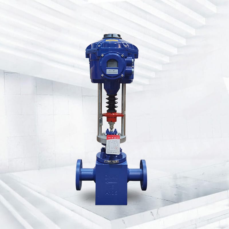
For applications requiring precise low-flow modulation, a compact single-seat control valve may provide an engineering starting point. Final suitability depends on the selected trim, differential pressure, shutoff requirement, medium, actuator, and installed operating range.
Choosing Linear, Equal-Percentage, or Characterized Rotary Trim
No single flow characteristic always produces the best control valve rangeability.
| Trim characteristic | Potential advantage | Selection questions |
| Linear | Predictable Cv change when valve pressure drop remains stable | Will differential pressure actually remain stable across the load range? |
| Equal percentage | Smaller capacity changes near closed and greater capacity at high travel | Will the installed pressure-drop pattern convert it into an acceptable installed characteristic? |
| Characterized V-port | High capacity with a defined rotary opening profile | What are the minimum controllable angle, seat clearance, torque, recovery factor, and installed gain? |
| Restricted or micro-flow trim | Better travel utilization at low required Cv | Can the passages handle the fluid cleanliness, viscosity, particles, and erosion risk? |
| Multi-stage trim | Distributes severe pressure reduction while controlling flow | Will small passages plug, and is each stage suitable for all operating cases? |
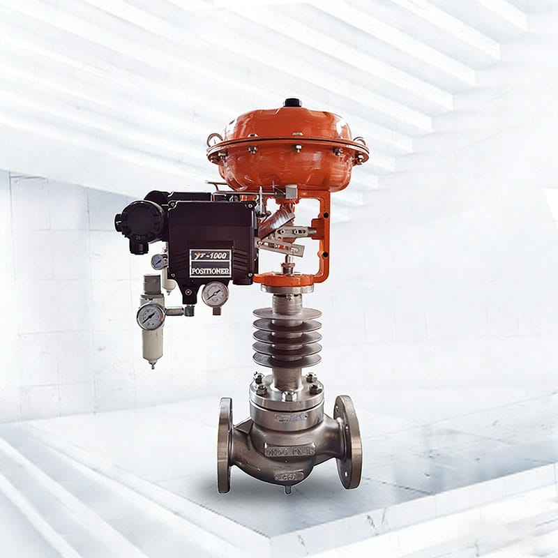
A pneumatic V-port control ball valve can offer modulating rotary control in suitable services. However, V-port geometry alone does not guarantee a particular installed turndown. Valve-specific Cv-versus-angle data, actuator resolution, differential pressure, and process conditions must be reviewed.
Buyers should compare suitable industrial control valve options only after defining the required minimum and maximum controllable Cv.
Actuator and Positioner Limits
Published control valve rangeability normally focuses on the valve body and trim. The process experiences the performance of the complete assembly.
Actuator sizing
The actuator must provide adequate thrust or torque at every credible condition, including maximum differential pressure, shutoff, startup, abnormal pressure imbalance, and packing friction.
An actuator that is only marginally sized may fail to follow small command changes or may move unpredictably when accumulated force is finally overcome.
Positioner resolution
A positioner should detect and correct small deviations without creating constant hunting. Its tuning must match the actuator volume, valve friction, booster arrangement, process speed, and controller behavior.
Linkage and feedback
Rotary linkages, stem connections, couplings, and feedback arms can introduce lost motion. Feedback should represent actual closure-member position as accurately as practical.
Dead band and friction
Dead band means the input can change without producing an immediate output movement. High friction may then cause the valve to jump when the available actuator force exceeds resistance.
These effects can make the real minimum controllable movement much larger than the theoretical trim increment, reducing installed control valve rangeability.
When One Valve Cannot Cover the Full Flow Range
Some processes genuinely require a wider operating range than one valve can provide reliably.
Examples include batch plants, startup and normal-production combinations, seasonal heating duties, reactor feeds, compressor recycle systems, and lines that must support both pilot and full-capacity operation.
Possible engineering arrangements include:
Restricted trim in a standard body
This approach reduces maximum Cv while preserving a suitable body size, pressure class, and connection arrangement. It can improve usable travel but must still satisfy maximum flow.
Two valves in parallel
A smaller valve handles minimum and normal flow, while a larger valve opens as demand rises. The sequencing logic must avoid discontinuities, interaction, and unnecessary cycling.
Separate startup and operating valves
A dedicated startup valve may handle an unusual pressure ratio or low-flow condition that does not occur during normal production.
Pressure regulation before the control valve
Managing upstream or downstream pressure can reduce extreme variation in valve differential pressure. The effect on system capacity, safety, energy, and relief conditions must be reviewed.
Variable-speed equipment
In some systems, coordinated pump or compressor speed control can reduce the pressure the valve must dissipate. The valve still needs sufficient authority and stable operation across the revised range.
The best arrangement should be selected through system analysis rather than attempting to obtain unlimited control valve rangeability from one oversized valve.
A Worked Rangeability Example
Consider a hypothetical process with these required flow coefficients:
| Operating case | Required Cv |
| Minimum stable production | 1.2 |
| Normal production | 12 |
| Maximum production | 36 |
The process requires a theoretical Cv ratio of:
36 ÷ 1.2 = 30:1
Selecting a valve with a published control valve rangeability of 50:1 appears sufficient. That conclusion is incomplete.
Suppose the selected valve has a rated Cv of 80. Maximum production uses only 45% of rated capacity, while the minimum case uses 1.5%. The valve may spend much of its life close to the seat, where friction and positioner resolution restrict control.
A restricted trim with a rated Cv closer to the actual maximum requirement may use more travel at every operating point. Although both trims may carry the same published ratio, the restricted trim can provide better installed control because it aligns available stroke with required capacity.
The final decision must still check noise, velocity, cavitation, actuator margin, shutoff, and process dynamics. If local liquid pressure can cross vapor pressure at low travel, review the control valve cavitation and flashing guide.
A Practical Selection Workflow
Use the following sequence to evaluate control valve rangeability without relying on the catalog ratio alone:
- Define simultaneous operating cases. Record minimum, normal, and maximum flow with their corresponding pressures, temperatures, and fluid properties.
- Calculate required Cv or Kv for every case. Include choked-flow, cavitation, flashing, and fitting corrections where applicable.
- Calculate the required flow-coefficient ratio. Compare maximum required Cv with minimum required Cv.
- Review valve-specific trim data. Obtain Cv at multiple travel positions rather than only the rated value.
- Estimate installed differential pressure. Determine how valve pressure drop changes with system flow.
- Plot the installed characteristic. Compare actual flow against travel across the required range.
- Check usable travel. Avoid a selection that places normal operation excessively close to the seat or full-open stop.
- Evaluate the complete assembly. Include actuator force, positioner resolution, friction, feedback, shutoff, and fail action.
- Check severe-service risks. Evaluate velocity, noise, cavitation, flashing, erosion, and vibration.
- Compare alternative arrangements. Consider restricted trim, another valve architecture, parallel valves, or process-pressure changes.
- Define acceptance criteria. Specify the required operating cases, predicted travel, rangeability basis, and testing or documentation requirements.
- Validate after commissioning. Compare valve command, actual travel, flow, pressure, and process response under real operating conditions.
Installed-gain analysis can provide a more meaningful view of loop behavior than a single rangeability ratio. The ISA guidance on control valve installed gain explains why valve style, pressure distribution, and installed characteristic should be evaluated together.
Data Required in a Control Valve RFQ
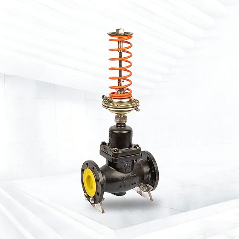
A complete request for quotation should contain enough information to verify both capacity and minimum-flow control.
| Data group | Information to provide |
| Fluid | Name, composition, phase, density, viscosity, vapor pressure, solids, corrosive properties |
| Operating cases | Minimum, normal, maximum, startup, shutdown, cleaning, and upset flow |
| Pressure | Corresponding inlet and outlet pressure for every case, identified as gauge or absolute |
| Temperature | Actual temperature for each operating case |
| Piping | Line size, schedule, reducers, expanders, elbows, and available straight run |
| Control duty | Flow, pressure, temperature, or level control objective and required response |
| Flow range | Required minimum and maximum controllable flow, not only design maximum |
| Valve requirements | Shutoff class, flow direction, rangeability requirement, characteristic, body material, connections |
| Actuation | Pneumatic or electric, supply condition, signal, fail position, stroking time, accessories |
| Reliability limits | Noise, vibration, cavitation, erosion, leakage, and maintenance interval |
| Documentation | Sizing sheets, Cv tables by travel, material records, inspection, testing, and applicable standards |
Ask the supplier to identify whether a stated ratio refers to inherent control valve rangeability, valve-assembly turndown, or predicted installed controllable range.
FAQ
What does control valve rangeability mean?
Control valve rangeability is the ratio between the maximum and minimum controllable flow coefficients over which the valve follows its stated inherent characteristic within defined limits. It is normally determined with constant pressure drop and does not automatically equal installed process turndown.
How is control valve rangeability calculated?
A simplified calculation divides maximum controllable Cv by minimum controllable Cv. For example, a maximum controllable Cv of 60 and minimum controllable Cv of 1.2 produce a ratio of 50:1.
Is rangeability the same as turndown?
No. Rangeability primarily describes inherent valve and trim capability. Turndown describes the usable maximum-to-minimum operating range of the valve assembly or installed process. Installed turndown is affected by pressure variation, actuator resolution, friction, leakage, process dynamics, and usable travel.
Does a higher rangeability always mean better control?
No. A high published ratio is useful only when the selected valve uses an appropriate travel range and the actuator, positioner, piping, and process allow stable operation. An oversized valve with a high ratio may control worse than a properly sized valve with a lower published ratio.
Which flow characteristic has the best rangeability?
There is no universal answer. Equal-percentage trim often supports broad load variation, but the correct characteristic depends on valve pressure-drop behavior and the desired installed response. Linear or characterized rotary trim may perform better in other systems.
Can an oversized valve reduce installed rangeability?
Yes. Oversizing can place normal and minimum operation close to the seat, where friction, mechanical clearance, leakage, and positioner resolution become significant. This reduces usable travel and may cause unstable control.
What should be checked at minimum flow?
Check required Cv, predicted travel, differential pressure, velocity, noise, cavitation or flashing risk, actuator resolution, friction, permissible leakage, and whether the process can maintain stable feedback at that flow.
Can two control valves be used for a very wide flow range?
Yes. A smaller and larger valve can be installed in parallel when one valve cannot provide the required range reliably. Valve sequencing, control logic, pressure interaction, shutoff, and transition between valves must be engineered carefully.
Is seat leakage included in the rangeability ratio?
No. Minimum controllable flow and closed-valve leakage are different values. A valve can meet a specified leakage class without being capable of accurately regulating a flow close to that leakage quantity.
What should a manufacturer provide to verify rangeability?
Request the rated and minimum controllable Cv, Cv-versus-travel data, inherent characteristic, rangeability definition, predicted travel for every operating case, installed sizing calculations, actuator and positioner details, and any assumptions used.
Conclusion
Control valve rangeability is a useful starting point, but it is not a guarantee of installed process control. The catalog ratio describes valve behavior under defined conditions. Real turndown depends on the required Cv range, changing differential pressure, usable travel, trim characteristic, actuator resolution, friction, leakage, piping, and process dynamics.
A dependable selection begins with simultaneous minimum, normal, and maximum operating cases. Calculate the required Cv for each case, compare valve-specific travel data, predict the installed characteristic, and verify severe-service risks before choosing the body and trim.
When the required flow range is too wide for one valve, restricted trim, parallel valves, separate startup control, or system-pressure changes may provide a more stable solution than oversizing.
For an application-specific rangeability review, submit the complete operating data. A full dataset allows valve capacity, minimum-flow control, trim, actuator, pressure drop, noise, and reliability to be evaluated as one system.