A chemical plant control valve is part of the process containment and control system, not an isolated catalog item. It may throttle corrosive liquid, toxic vapor, flammable solvent, polymerizing feed, slurry, steam, or inert gas while responding to normal control commands and protective trips.
Reliable chemical plant control valve selection begins with the complete operating envelope and the consequence of failure. Chemistry, concentration, temperature, pressure, phase, solids, leakage limits, hazardous-area classification, fail action, and maintenance practice all influence the final assembly.
This guide gives process engineers, instrumentation teams, maintenance planners, and buyers a practical way to specify a chemical plant control valve without inventing performance claims or hiding uncertainty behind a generic severe-service note.
Table of Contents
Start with the Process Function and Hazard

For a chemical plant control valve, define what the valve controls: flow, pressure, temperature, level, reactor feed, utility supply, venting, recycle, or protective isolation. Then record what happens if the valve fails open, closed, stationary, or slowly. A control problem and a containment failure have different consequences.
For each chemical plant control valve, connect the tag to the P&ID, control narrative, relief study, interlock description, and process hazard review. The selection should support the intended safeguard without claiming that a standard control valve replaces an independent protection layer.
Include startup, shutdown, cleaning, regeneration, nitrogen purging, emergency depressurization, and blocked-outlet cases. The most severe pressure drop or chemical exposure may occur outside normal production.
Build a Complete Chemical Exposure Profile
For a chemical plant control valve, list every component in the stream, including water, oxygen, chlorides, sulfur species, solvents, catalysts, inhibitors, cleaning agents, and credible contaminants. State concentration ranges and whether mixing, flashing, evaporation, or condensation can change local chemistry.
A chemical plant control valve can experience different environments at the inlet, restriction, body cavity, packing box, and outlet. Pressure reduction may create a colder flashing zone or concentrate nonvolatile species. Stagnant cavities may corrode even when the main flow keeps deposits moving.
Use service-specific materials data and the project materials authority. AMPP corrosion resources and NIST materials data are useful starting points, but they do not replace an application review.
Containment and Emissions Are Separate Requirements
For a chemical plant control valve, internal seat leakage, external stem leakage, and pressure-boundary integrity are different requirements. Define each one with a test basis and consequence. A tight seat does not prove low fugitive emissions, and qualified packing does not make the valve an isolation boundary.
For a chemical plant control valve handling toxic or flammable media, specify packing arrangement, bellows or secondary containment where justified, leak detection, drains, vents, and access for monitoring. The complete assembled valve must meet the stated test, not merely use a named packing material.
Useful references include ISO 15848-1 and US EPA equipment leak guidance. Confirm jurisdiction, edition, measurement method, pressure, temperature cycles, and acceptance limit.
Choose Materials Component by Component
For a chemical plant control valve, select body, bonnet, plug or ball, seat, cage, stem, guides, shaft, packing, gaskets, fasteners, liners, and coatings for their actual exposure. Generic notes such as “stainless trim” leave critical small parts undefined.
A chemical plant control valve may need a corrosion-resistant pressure boundary but a harder trim, or a lined body with a different shaft and seal system. Check galvanic pairing, galling, thermal expansion, impact toughness, weld repair, and traceability.
Use the control valve material selection guide and the packing selection guide to document each component instead of upgrading the whole assembly by habit.
Check Sizing Across Batch and Continuous Operation
For a chemical plant control valve, calculate minimum, normal, maximum, startup, shutdown, and upset conditions. Batch plants may operate with changing vessel head, composition, temperature, and vapor pressure. A valve sized only for the largest batch flow may spend most cycles near the seat.
For a chemical plant control valve, predict travel, velocity, noise, cavitation, flashing, and choked flow for every case. Review the installed characteristic with pumps, vessels, exchangers, and downstream pressure.
The control valve sizing guide explains the data workflow, while ISA-75 resources identify recognized control-valve calculation standards.
Define Fail Action from the Cause-and-Effect Logic
For a chemical plant control valve, fail-open, fail-closed, or fail-in-place should follow the plant cause-and-effect logic. Loss of signal, power, instrument air, or trip-solenoid energy can produce different results. State the safe process condition as an actual flow path and final position.
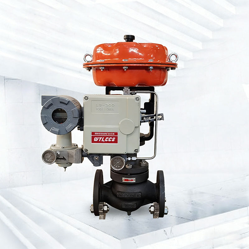
The chemical plant control valve actuator must reach that position against maximum process force, packing friction, and credible utility pressure. Volume tanks, boosters, quick exhaust valves, and solenoids should be sized and tested as part of the same chain.
Review the fail action guide. Do not infer functional safety capability from a component label without the required project assessment and records.
Specify Accessories for the Classified Area
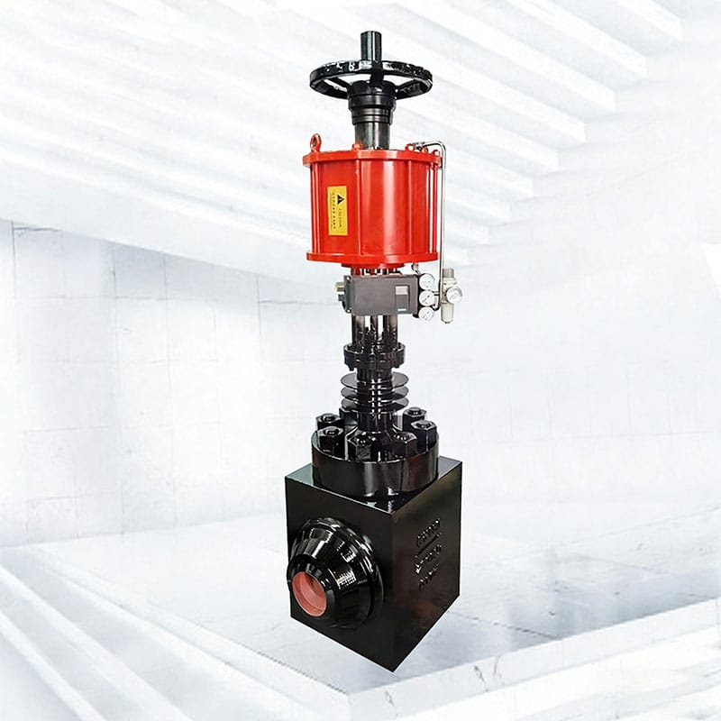
A chemical plant control valve may include positioners, solenoids, switches, transmitters, regulators, tubing, cable entries, and junctions need compatible area classification, ambient range, enclosure protection, and materials. Certification scope must match the exact configuration.
For a chemical plant control valve, define signal type, diagnostic access, grounding, ingress protection, instrument-air quality, minimum dynamic supply pressure, and cybersecurity or network requirements where applicable.
Consult the project electrical authority and authoritative schemes such as IECEx equipment certification information. Never claim a hazardous-area approval unless the supplied model and accessories are documented.
Design Maintenance Access Before Purchase
Around a chemical plant control valve, provide space to remove the actuator, bonnet, trim, packing, and adjacent insulation. Route drains and vents to safe systems. Locate handwheels, filters, gauges, and positioner interfaces where technicians can work without unsafe reach or dismantling nearby equipment.
A maintainable chemical plant control valve has identified wear parts, suitable lifting points, flushing or decontamination instructions, and an isolation plan. Consider cavity drainage and residual chemical exposure before choosing a valve style.
Baseline positioner data, travel response, leakage results, and final settings should be stored for later troubleshooting.
Chemical Service Selection Matrix
| Service feature | Primary risk | Engineering response |
|---|---|---|
| Corrosive clean liquid | Body or trim attack | Component-level materials and local concentration review |
| Toxic vapor | External leakage | Qualified stem sealing, monitoring, and defined test |
| Polymerizing fluid | Cavity blockage and sticking | Low-retention geometry, flushing, temperature control |
| Flammable solvent | Containment and ignition sources | Leakage control and suitable classified-area accessories |
| Chemical slurry | Erosion plus corrosion | Open passage, velocity control, wear and chemistry review |
Use the matrix to identify the dominant failure mechanism for each chemical plant control valve. It is a screening step; final selection still requires the exact chemistry, hydraulic calculation, and project risk controls.
Testing and Documentation for Handover
Chemical plant control valve factory acceptance should verify tag identity, materials, pressure tests, specified seat and external leakage tests, actuator mounting, calibration, fail state, travel limits, accessories, and configuration. Critical service may justify witnessed testing or material verification.
For every chemical plant control valve, record test conditions and measured results rather than a pass statement alone. Final files should include datasheets, drawings, calculations, certificates, bills of material, manuals, configuration, deviations, and spare-parts lists.
Pressure-boundary and leakage references may include ASME B16.34 and ISO 5208, subject to the project’s governing code.
RFQ Checklist for a Comparable Technical Offer
- Complete fluid composition and operating, cleaning, startup, shutdown, and upset cases.
- Valve function, calculated sizing cases, predicted travel, noise, cavitation, flashing, and velocity.
- Exact pressure-boundary, trim, sealing, liner, coating, and fastener materials.
- Seat leakage, fugitive-emission, pressure-test, fail-action, stroke-time, and diagnostic requirements.
- Accessory scope, area classification, utilities, environmental conditions, mounting, tubing, and wiring.
- Inspection points, documents, certificates, deviations, recommended spares, and maintenance constraints.
A clear RFQ gives every bidder the same technical basis. Ask suppliers to state assumptions and deviations for the chemical plant control valve rather than silently substituting a standard arrangement.
Frequently Asked Questions
Which valve style is best for chemical service?
No single style is best. Globe, ball, eccentric rotary, butterfly, diaphragm, lined, or ceramic designs suit different combinations of control range, pressure drop, chemistry, solids, containment, and maintenance.
Does corrosion-resistant alloy guarantee long life?
No. Concentration, temperature, velocity, deposits, material condition, galvanic pairs, and mechanical wear can still cause failure.
Can a control valve provide emergency isolation?
Only when the project has assessed the complete assembly, test requirements, leakage, actuator, utilities, and safety architecture for that function. A normal throttling valve should not be assumed to be an isolation layer.
What information is needed for actuator sizing?
Provide pressure cases, flow direction, valve forces or torque, packing friction, seat load, minimum utility pressure, fail action, stroke time, and accessory restrictions.
What documents should be retained after commissioning?
Keep final datasheets, drawings, material records, calculations, test results, configuration, deviations, manuals, spares lists, and baseline diagnostic data.
Connect the Valve to the Plant Risk Controls

A successful chemical plant control valve connects process chemistry, hydraulic duty, containment, actuation, classified-area equipment, maintenance, and verification. The selection is credible when assumptions are visible and acceptance criteria can be tested.
For an application review, provide Phileda with the process cases, full composition, materials restrictions, leakage requirements, fail action, utilities, and document list through the contact page.