A power plant control valve may regulate main steam, feedwater, condensate, extraction steam, desuperheating water, turbine bypass, boiler drains, or auxiliary utilities. These services share a plant boundary but differ greatly in pressure ratio, temperature, phase change, cycling, required response, and failure consequence.
Sound power plant control valve selection starts by identifying the system function and all operating modes. Startup and shutdown can create the highest differential pressure, while base-load operation may create the longest exposure to temperature and small travel. Cycling plants add frequent thermal and mechanical transients.
This guide helps power-generation engineers and buyers separate valve duties, evaluate severe-service mechanisms, size actuation, and define tests without applying one generic high-pressure specification to the entire station.
Table of Contents
Classify the Valve by Plant System

For each power plant control valve, create a system map covering boiler or heat-recovery steam generator, turbine, condenser, feedwater train, condensate system, drains, vents, and auxiliary steam. For every tag, state whether the power plant control valve is continuous control, startup control, bypass, pressure protection support, or sequencing duty.
For a power plant control valve, list minimum, normal, maximum, startup, shutdown, trip, warm-restart, cold-restart, and low-load conditions. Include upstream and downstream pressure, temperature, flow, phase, superheat, and expected duration.
Use the control narrative and heat balance together. A valve selected from one design point can miss a low-flow high-pressure-drop condition that controls trim design and actuator force.
Steam Valves Face Temperature and Velocity
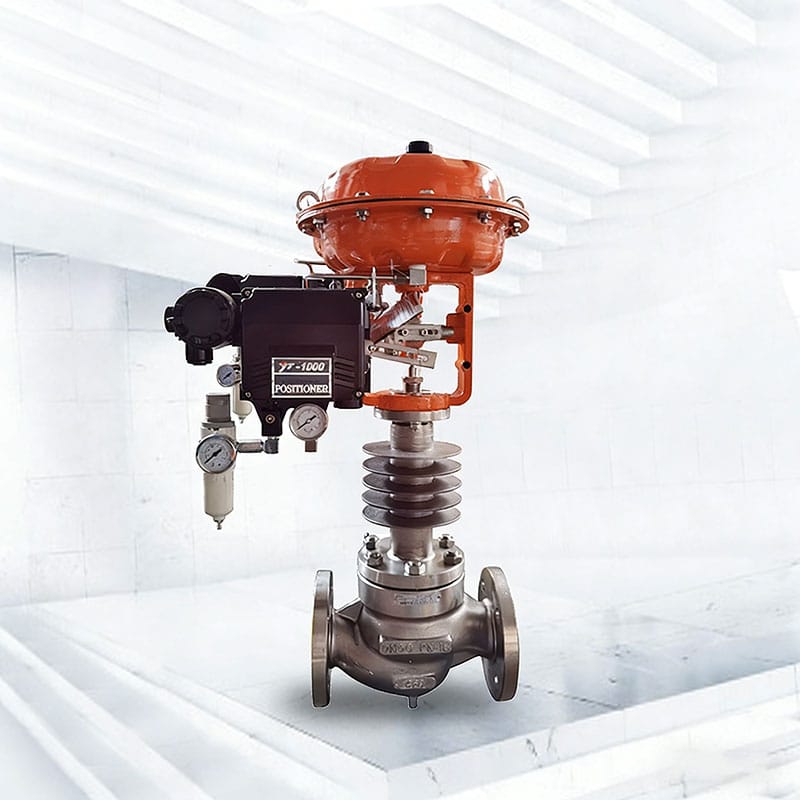
Power plant control valve steam velocity and pressure ratio can produce choked flow, aerodynamic noise, vibration, erosion, and high outlet temperature. Superheated, saturated, and wet steam behave differently, and condensate droplets can damage downstream surfaces.
For a steam power plant control valve, calculate every flow case with the applicable gas or steam method. Check outlet Mach number, body velocity, downstream pipe velocity, acoustic prediction, and the location of any pressure-reducing stages.
Materials must retain strength and dimensional stability at temperature. Review body rating, stem growth, guide clearance, hardfacing, packing, gasket, bonnet design, and warm-up procedure. ASME codes and standards provide the governing framework selected by the project.
Feedwater and Condensate Need Pressure-Recovery Checks
A power plant control valve for feedwater or condensate handle liquids near changing saturation conditions. A pressure drop can cause cavitation, flashing, or gas breakout. Startup water temperature and pressure may be more damaging than rated load.
A power plant control valve in liquid service should be checked for cavitation index, flashing, velocity, erosion location, and downstream piping. Staged trim may control pressure reduction, but it must remain effective at actual travel and flow.
The cavitation versus flashing guide explains why cavitation can be managed by recovery design while flashing continues downstream.
Turbine Bypass Service Is a Dynamic System
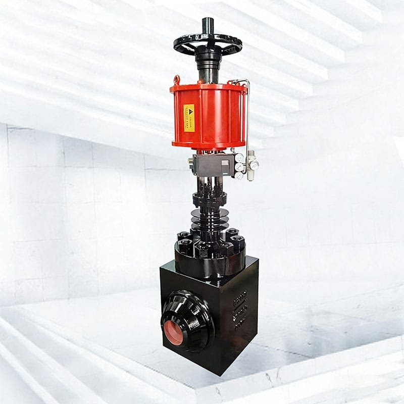
A power plant control valve in a turbine bypass station coordinates a steam pressure-reducing valve, desuperheating water, spray nozzles, downstream pipe, temperature measurement, and protection logic. The valve alone cannot guarantee outlet steam conditions.
For a bypass power plant control valve, evaluate maximum capacity, minimum controllable steam flow, fast opening, actuator dynamics, pressure staging, noise, outlet velocity, water injection limits, mixing distance, and condensate drainage.
Place temperature sensing where water has evaporated and steam is mixed, while keeping delay acceptable. Poor sensor location can drive overspray or unstable control. Refer to ISA-75 control-valve standards for recognized sizing and test methods.
Drain and Vent Valves Experience Transition Duty
A power plant control valve on drain or vent service can remain closed at load, then pass flashing condensate, wet steam, debris, or high differential pressure during startup. Short duration does not mean low severity. Seat leakage can also waste energy or heat downstream piping.
The power plant control valve specification should define warm-up sequences, flow direction, debris risk, cycling frequency, shutoff conditions, and whether the valve throttles or only sequences. Avoid using tight leakage as a substitute for a suitable drain arrangement.
Provide accessible strainers, warm-up bypasses, traps, or inspection points where the system design requires them.
Thermal Cycling Controls Materials and Clearances
For a power plant control valve, thermal transients change clearances and impose differential expansion between body, bonnet, stem, cage, seat, and actuator mounting. Rapid temperature change can distort parts or create temporary rubbing even when steady-state dimensions are correct.
For a power plant control valve, verify material grades, heat treatment, impact requirements, weld procedures, hardfacing pairs, and calculated clearances through the complete temperature range.
Insulation should protect personnel and reduce heat loss without covering the packing box, actuator, positioner, vents, or diagnostic access. The material selection guide supports the component review.
Actuator Response Must Match the Protection Function
Power plant control valve actuator sizing must include maximum differential-pressure force, seat load, packing friction at temperature, spring force, and dynamic requirements. Minimum available air or electrical supply during a plant event is more relevant than normal utility conditions.
A protective power plant control valve may need a defined full-stroke time, but response should be evaluated with the positioner, solenoid, tubing, booster, volume tank, and process load. Fast movement that creates water hammer or seat impact is not automatically better.
Use the actuator sizing guide and verify fail action with the plant cause-and-effect logic.
Noise and Vibration Need a Source-Based Solution
Noise may originate at the trim, expand in the downstream pipe, excite structural modes, or radiate through connected equipment. Vibration can also come from cavitation, flashing, unstable flow, unsupported piping, or acoustic coupling.
For every power plant control valve, identify the source before selecting low-noise trim. Check predicted sound pressure, frequency concerns, outlet velocity, pipe wall, reducers, supports, and downstream fittings.
The control valve noise guide explains trim and system measures. Occupational exposure requirements may include OSHA noise guidance or the applicable local regulation.
Power Plant Application Comparison
| Plant duty | Controlling risk | Key specification focus |
|---|---|---|
| Main or auxiliary steam | Choked flow, noise, thermal load | Staged pressure drop, materials, outlet velocity |
| Feedwater control | Cavitation, flashing, rangeability | All startup and load cases, trim staging |
| Turbine bypass | Fast dynamics and desuperheating | Integrated valve-water-pipe-control response |
| Boiler drains | Transition flow, debris, leakage | Startup cases, erosion path, maintainable seat |
| Condensate control | Low pressure and gas breakout | NPSH context, flashing, installed characteristic |
This comparison prevents one power plant control valve standard from erasing important service differences. Standardize documents and interfaces while allowing hydraulic and material designs to follow the duty.
Commissioning Across Cold and Hot Conditions
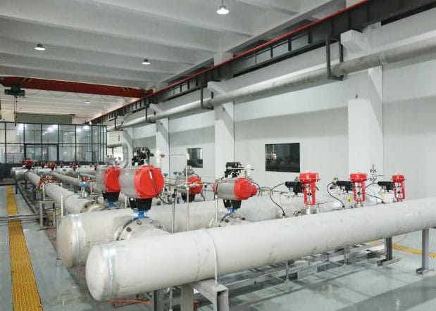
Power plant control valve factory tests should verify pressure boundary, leakage, materials, travel, calibration, fail action, accessories, and specified stroke time. Record air pressure, signal, position, and test conditions.
At site, commission a power plant control valve through cold checks, utility checks, loop tests, and controlled hot operation. Confirm flow direction, pipe cleanliness, supports, insulation limits, warm-up, drains, interlocks, and response at several load points.
Retain as-left configuration and baseline diagnostics. A workshop stroke at ambient temperature does not prove performance under hot differential pressure, so document what each test demonstrates.
Procurement and Maintenance Data Checklist
- System and control function, all load and transition cases, fluid phase, pressure, temperature, flow, and duration.
- Sizing results, predicted travel, pressure staging, noise, outlet velocity, cavitation, flashing, and downstream requirements.
- Exact body, bonnet, trim, stem, guide, packing, gasket, and hardfacing materials.
- Actuator force or torque, minimum utility supply, fail state, stroke time, solenoid, booster, and volume accessories.
- Pressure, leakage, calibration, response, material, and functional tests with witness points.
- Final drawings, calculations, certificates, configuration, manuals, deviations, and recommended critical spares.
A complete data package makes each power plant control valve offer comparable and provides maintenance with a defensible baseline. Pressure-boundary testing may use ISO 5208 or project-specific requirements.
Frequently Asked Questions
Why is startup often the worst valve condition?
Startup can combine low flow with maximum pressure drop, colder material clearances, flashing liquid, debris, and rapidly changing temperature.
Is multistage trim always required in power plants?
No. It is justified when the calculated pressure ratio, cavitation, noise, velocity, or erosion risk requires staged reduction across the actual operating range.
Can a turbine bypass valve be sized without the spray-water system?
No. Steam pressure reduction, water injection, evaporation, sensing, pipe length, and control logic interact and should be reviewed as a system.
What causes hot valves to stick?
Thermal expansion, distorted piping, guide clearance, deposits, packing friction, stem alignment, or material pairing can restrict movement. Preserve diagnostic evidence before adjustment.
Which baseline tests are most valuable?
Keep pressure and leakage results, calibration, fail test, stroke time, positioner configuration, valve signature, materials records, and hot commissioning observations.
Specify Each Duty Instead of a Plant Standard
Successful power plant control valve engineering separates steam, water, bypass, drain, and auxiliary duties, then connects each one to the hydraulic, thermal, mechanical, and protection requirements.
Provide Phileda with the heat-balance cases, process datasheet, control narrative, materials, fail action, utilities, and testing requirements through the contact page for a duty-specific review.