A boiler feedwater control valve regulates water entering a boiler or steam generator while upstream pump pressure, downstream drum pressure, temperature, and required flow change across startup and load. The valve may face its highest differential pressure at low flow, not at maximum production.
Reliable boiler feedwater control valve selection therefore requires multiple hydraulic cases, prediction of travel, cavitation and flashing analysis, pressure-staging review, actuator-force calculation, and coordination with the feedwater pump and control strategy.
This guide helps power and process engineers specify a boiler feedwater control valve that can control startup and normal load without treating hard trim or oversized capacity as a universal solution.
Table of Contents
Map Startup, Low Load, and Rated Load Separately

For a boiler feedwater control valve, prepare cases for cold startup, warm startup, low load, normal load, peak load, pump changeover, boiler trip, recirculation, and any bypass arrangement. Record upstream and downstream pressure, water temperature, flow, density, vapor pressure, and duration.
For a boiler feedwater control valve, calculate the actual pressure drop from pump discharge to drum or economizer inlet. Do not use pump shutoff pressure for every case or assume design pressure equals operating differential pressure.
If separate startup and main valves are used, define the transfer point and overlap. If one valve covers the whole range, prove that it has useful travel and stable control at both the minimum startup flow and rated load.
Understand Where Cavitation Begins
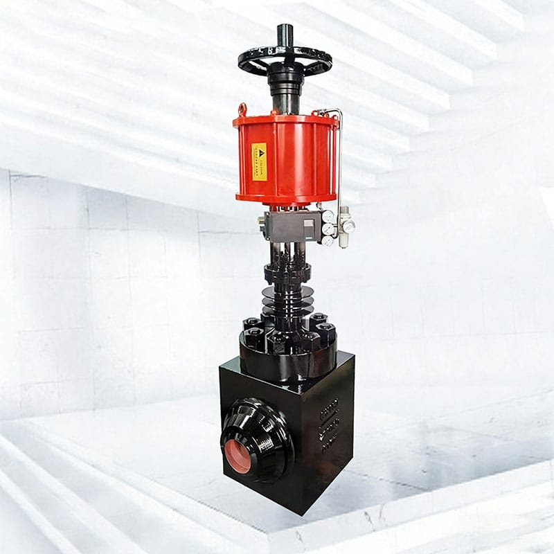
For a boiler feedwater control valve, cavitation begins when local pressure falls below vapor pressure and bubbles later collapse after pressure recovery. Collapse near trim or body surfaces produces noise, vibration, and material damage. Feedwater temperature makes vapor-pressure accuracy important.
A boiler feedwater control valve cavitation review should calculate each load case with valve-specific recovery factors. Check the trim outlet, body wall, downstream pipe, and operating travel where the final pressure recovery occurs.
Pressure staging can keep intermediate pressures above the critical threshold, but only if stages remain effective at actual flow and travel. The cavitation versus flashing guide explains the mechanism.
Distinguish Flashing from Cavitation
In a boiler feedwater control valve, flashing occurs when downstream pressure remains below vapor pressure, so vapor does not collapse back into liquid inside the recovery zone. The two-phase mixture continues downstream at high volume and velocity.
For a boiler feedwater control valve, distinguish flashing from cavitation because the remedies differ. Hard materials may slow erosion but cannot condense vapor when the downstream thermodynamic condition keeps it stable.
Review outlet size, body geometry, downstream pipe diameter, reducers, erosion allowance, and drainage. A larger outlet or angle-body arrangement may direct the two-phase jet more safely.
Use Pressure Staging Across the Actual Travel Range
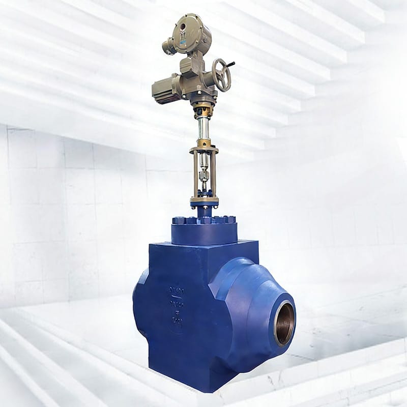
Boiler feedwater control valve multistage trim divides the total pressure drop so no single restriction experiences the full recovery. Series passages, cages, tortuous paths, or axial stages use different mechanisms and have different limits for particles, rangeability, maintenance, and clogging.
Boiler feedwater control valve staging must be checked at startup, low load, rated load, and maximum flow. A stage arrangement designed for one Cv can lose pressure distribution when the valve operates near closed or when passage Reynolds number changes.
Request the pressure profile, minimum passage size, predicted exit velocity, stage loading, and inspection method. The control valve trim selection guide supports the mechanical comparison.
Size for Rangeability, Not Only Maximum Cv
For a boiler feedwater control valve, maximum Cv ensures capacity, but minimum controllable Cv determines whether startup flow can be regulated without hunting or seat-zone erosion. Oversizing concentrates normal control into a small portion of travel.
For a boiler feedwater control valve, calculate required Cv and predicted travel for every case, then review the installed characteristic with pump curve, drum pressure, economizer losses, and recirculation logic.
Use the control valve sizing guide and relevant ISA-75 standards resources. A split-range startup valve may be justified when one trim cannot provide both low-flow resolution and full-load capacity.
Choose Materials for Erosion and Thermal Cycling
A boiler feedwater control valve can face cavitation erosion, flashing erosion, corrosion, particle damage, and thermal cycling. Body and trim materials face different mechanisms. Hardness alone does not define toughness, galling resistance, corrosion behavior, or repairability.
A boiler feedwater control valve material schedule should identify body, bonnet, plug, seat, cage, stem, guides, hardfacing, packing, and gaskets. Check material strength and clearances at both cold and hot conditions.
Boiler chemistry excursions, oxygen, pH, deposits, and startup debris should be included. Review control valve material selection and retain material certificates appropriate to project risk.
Check Actuator Force at the Worst Hydraulic Case
Boiler feedwater control valve actuator sizing must consider unbalanced hydraulic force, seat load, packing and guide friction, stem weight, spring force, and the pressure direction. The worst force can occur at shutoff, partial travel, or a pump transient.
For a boiler feedwater control valve, use minimum dynamic air pressure or minimum electrical output during the governing event. Confirm maximum actuator force does not overload the stem, seat, trim, or bonnet.
Fail action follows the boiler and pump protection philosophy. Test the complete positioner, solenoid, actuator, and utility path. The actuator sizing guide gives a structured calculation.
Coordinate the Valve with Pump and Boiler Controls
A boiler feedwater control valve interacts with feedwater pump speed or recirculation, drum level measurement, three-element control, economizer resistance, and boiler pressure. Poor coordination can make a correctly sized valve appear unstable.
A boiler feedwater control valve review should examine control authority across load, valve-pump interaction, transfer between startup and main paths, check-valve behavior, and the effect of rapid closure.
Avoid tuning around mechanical stiction or an oversized valve. Use aligned trends of demand, travel, actuator pressure, pump speed, drum level, and flow to identify the source.
Feedwater Design Options Compared
| Design option | Useful when | Main check |
|---|---|---|
| Single valve with severe-service trim | One valve can cover full flow range | Minimum travel, stage behavior, maintainability |
| Separate startup and main valves | Startup flow is far below rated flow | Transfer logic, overlap, isolation, two-valve leakage |
| Angle-body outlet | Two-phase outlet or erosion direction matters | Piping layout, outlet velocity, body wall protection |
| Multistage cage or axial trim | Large liquid pressure drop requires controlled recovery | Passage size, staging at all travel, debris sensitivity |
Use this comparison to select a boiler feedwater control valve arrangement around the operating envelope, not around a preferred construction.
Commission with Pressure and Travel Evidence
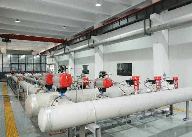
Boiler feedwater control valve factory acceptance should verify identity, materials, dimensions, pressure and leakage tests, calibration, fail action, travel, accessory function, and specified valve signature. Record test pressure, temperature where relevant, and actuator supply.
At site, commission the boiler feedwater control valve through cleaning confirmation, cold stroke, loop test, pump and interlock checks, controlled warm-up, startup flow, and increasing load. Trend upstream and downstream pressure, flow, travel, actuator output, vibration, and noise.
Preserve baseline data at stable conditions. A pass at full stroke does not demonstrate low-flow controllability or cavitation performance.
Specification and RFQ Checklist
- Cold startup, warm startup, low, normal, maximum, trip, and pump-changeover flow-pressure-temperature cases.
- Water properties, vapor pressure, calculated Cv, predicted travel, cavitation, flashing, velocity, and noise.
- Valve size, pressure class, flow direction, body and trim design, stage data, materials, and passage dimensions.
- Seat leakage, actuator-force cases, minimum utility pressure, fail action, stroke time, positioner, and solenoid.
- Piping, outlet size, reducers, drains, supports, cleaning, installation, and insulation requirements.
- Calculations, drawings, material records, pressure and leakage tests, calibration, diagnostics, manuals, and spares.
Energy-efficiency context is available from US Department of Energy steam-system resources. A clear boiler feedwater control valve RFQ lets suppliers return the same cases and declare assumptions. Pressure-boundary references may include ASME B16.34 and testing may reference ISO 5208 where contractually applicable.
Frequently Asked Questions
Why is low-load feedwater service severe?
Pump discharge can remain high while boiler pressure and required flow are low, creating a large pressure drop through a small opening.
Does hard trim stop cavitation?
Hard trim can resist some damage, but cavitation control requires appropriate pressure recovery and staging. It does not remove the hydraulic cause by itself.
When are two feedwater valves useful?
A smaller startup valve and larger main valve can provide better range coverage when one valve cannot control both extremes. Transfer logic and leakage must be engineered.
What determines actuator force?
Hydraulic pressure force, flow direction, seat load, packing and guide friction, spring force, valve position, and utility pressure all contribute.
Which commissioning trend is most useful?
Align flow, upstream and downstream pressure, valve command, actual travel, actuator output, pump condition, vibration, and noise on the same time base.
Protect the System Across Every Load Case
Successful boiler feedwater control valve engineering protects controllability and hardware from cold startup through rated load. It uses case-by-case hydraulics, effective pressure staging, suitable materials, adequate actuator force, and measured commissioning evidence.
Provide Phileda with the feedwater cases, pump and boiler pressures, temperature, water properties, control strategy, materials, fail action, and test requirements through the contact page.